Electrical installation
4.2 Terminal description
SINAMICS V20 Inverter
24 Operating Instructions, 07/2012, A5E03728167
Recommended cable cross-sections and screw tightening torques
Screw tightening torque (tolerance: ± 10%) Frame size Rated output
power
Cable cross-section
Mains and PE terminals Motor / DC / braking resistor /
output earth terminals
400 V
0.37 ... 0.75 kW 1.0 mm
2
A
1.1 ... 2.2 kW 1.5 mm
2
1.0 Nm
B 3.0 ... 4.0 kW 2.5 mm
2
1.0 Nm
1.5 Nm
C 5.5 kW 4.0 mm
2
7.5 kW 6.0 mm
2
D
11 ... 15 kW 10 mm
2
2.4 Nm
Maximum motor cable lengths
Frame size Maximum cable length
Unshielded cable Shielded cable
A, unfiltered 50 m 25 m
A, filtered 50 m 10 m
B 50 m 25 m
C 50 m 25 m
D 50 m 25 m
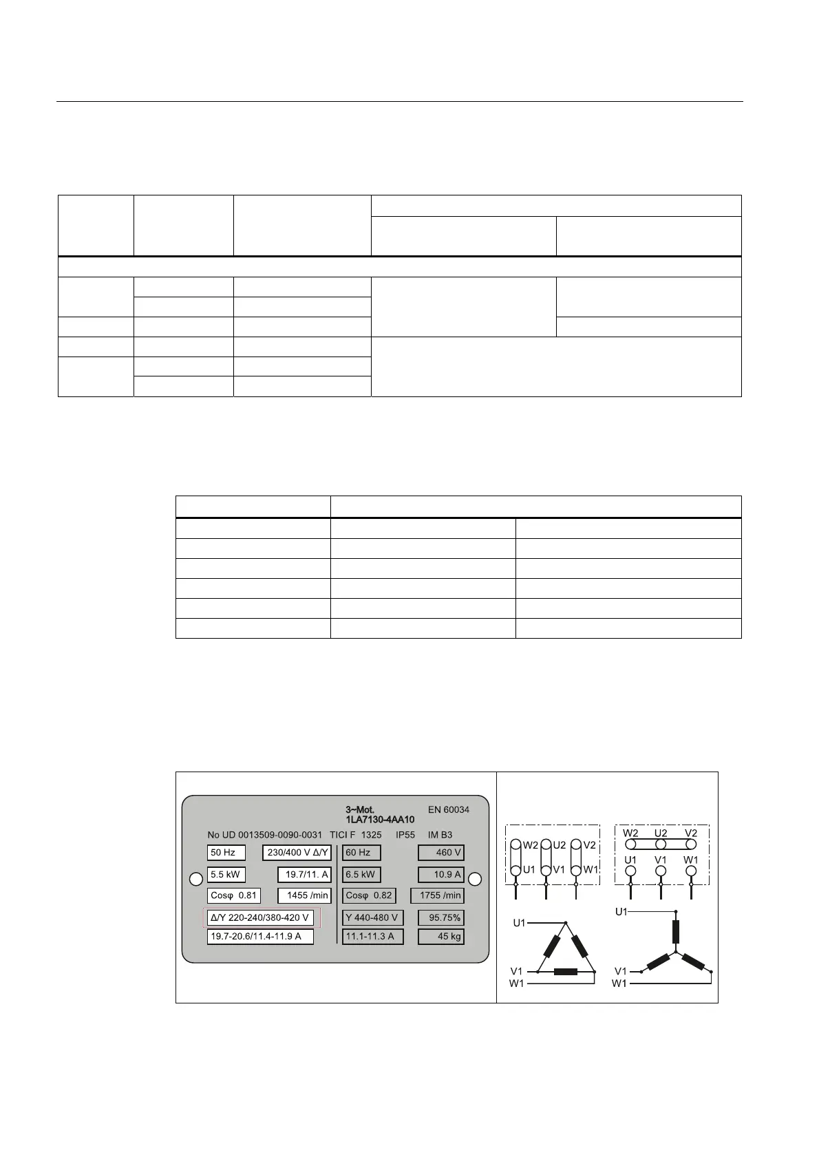
Star-delta connection of the motor
Select delta connection if either a 230 / 400 V motor on a 400 V inverter or a 120 / 230 V
motor on a 230 V inverter is supposed to operate at 87 Hz instead of 50 Hz.
5DWLQJSODWHZLWKPRWRUGDWD
'HOWDFRQQHFWLRQ
6WDUFRQQHFWLRQ

 Loading...


