Electrical installation
4.2 Terminal description
SINAMICS V20 Inverter
Operating Instructions, 07/2012, A5E03728167
25
User terminals
9 $, $2 9 3$,
1 ', ', ',
',&
9', 9 '2 '2
1&
'2
12
'2
&
'2
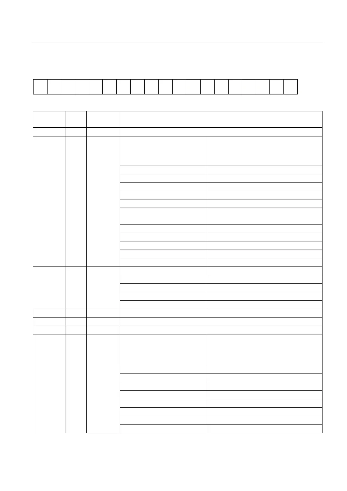
No. Terminal
marking
Description
1 10V 10 V output (tolerance ± 5 %) referred to 0V, maximum 11 mA, short circuit protected
Mode: AI1: Single-ended, bipolar current and voltage
mode
AI2: Single-ended, unipolar current and voltage
mode
Isolation to control circuit: None
Voltage range: AI1: -10 ... 10 V; AI2: 0 ... 10 V
Current range: 0 ... 20 mA (4 ... 20 mA software selectable)
Voltage mode accuracy: ± 5 % full scale
Current mode accuracy: ± 5 % full scale
Input impedance: Voltage mode: > 30 K
Current mode: 235 R
Resolution: 10-bit
Wire break detect: Yes
Threshold 0 ⇒ 1 (used as DIN): 4.0 V
Threshold 1 ⇒ 0 (used as DIN): 1.6 V
Analog
inputs
2
3
AI1
AI2
Response time (digital input mode): 4 ms ± 4 ms
Mode: Single-ended, unipolar current mode
Isolation to control circuit: None
Current range: 0 ... 20 mA (4 ... 20 mA - software selectable)
Accuracy (0 ... 20 mA): ± 1 mA
Analog
output
4 AO1
Output capability: 20 mA into 500 R
5 0V Overall reference potential for RS485 communication and analog inputs / output
6 P+ RS485 P +
7 N- RS485 N -
Mode: PNP (reference terminal low)
NPN (reference terminal high)
Characteristics values are inverted for NPN
mode.
Isolation to control circuit: 100 V DC (functional low voltage)
Absolute maximum voltage: ± 35 V for 500 ms every 50 seconds
Operating voltage: - 3 V ... 30 V
Threshold 0 ⇒ 1 (maximum): 11 V
Threshold 1 ⇒ 0 (minimum): 5 V
Input current (guaranteed off): 0.6 ... 2 mA
Input current (maximum on): 15 mA
Digital
inputs
8
9
10
11
12
DI1
DI2
DI3
DI4
DI C
2-wire Bero compatibility: No

 Loading...


