Commissioning
5.6 Function commissioning
SINAMICS V20 Inverter
Operating Instructions, 07/2012, A5E03728167
75
Parameter Function Setting
P1254 Auto detect Vdc switch-on levels This parameter enables / disables auto-detection of switch-on
levels for Vdc_max controller.
= 0: Disabled
= 1: Enabled (factory default)
It is recommended to set P1254 = 1 (auto detection of Vdc
switch-on levels enabled). Note that auto detection only works
when the inverter has been in standby for over 20s. When
P1240 = 0, P1254 is only applicable for frame size D
inverters.
WARNING
Braking resistors, which are to be mounted on the inverter, must be designed so that they
can tolerate the power dissipated. If an unsuitable braking resistor is used, there is a
danger of fire and the associated inverter will be significantly damaged.
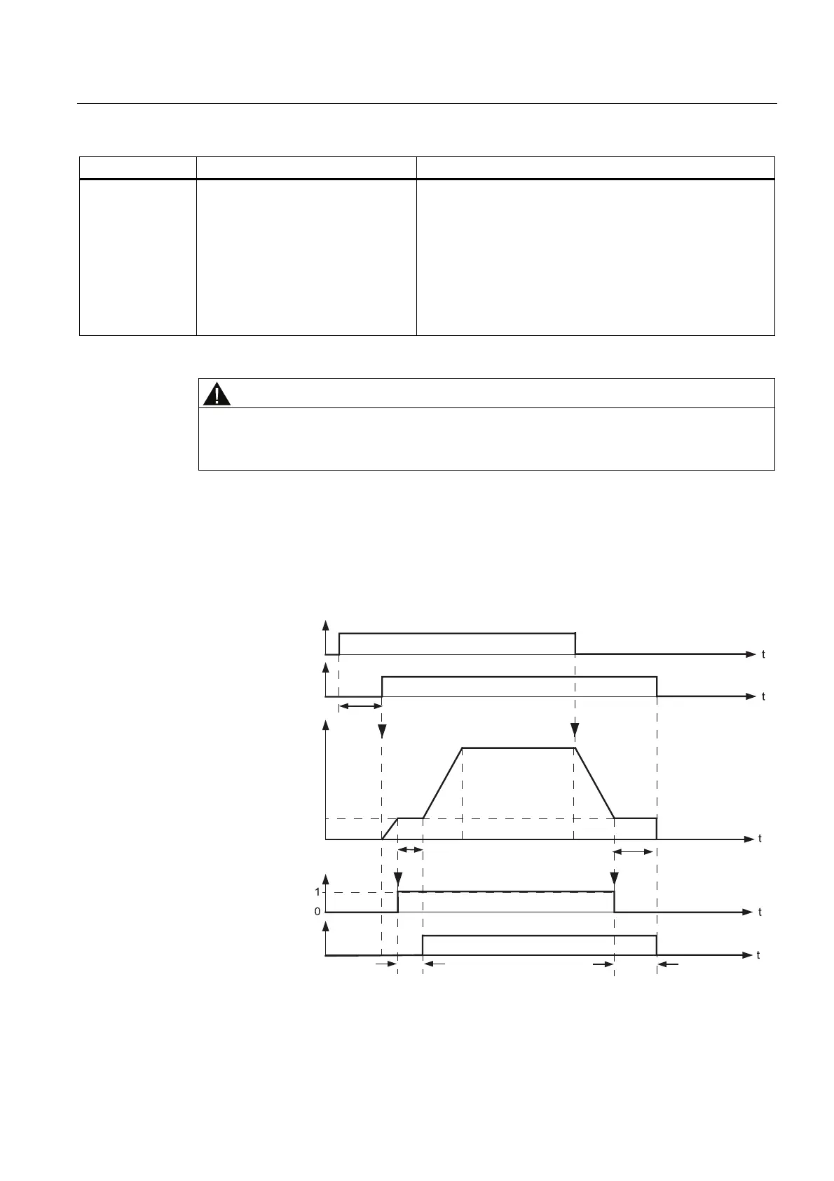
Motor holding brake
The motor holding brake prevents the motor from undesirable turning when the inverter is
switched-off. The inverter has internal logic to control a motor holding brake.
U&%LW
U%LW
0RWRUH[FLWDWLRQ
ILQLVKHG
%UDNH
VWDWXV
2SHQ
&ORVHG
%UDNHUHOHDVHWLPH %UDNHFORVLQJWLPH
212))2))
2))2))
21
3
3
3
I
I
PLQ
3

 Loading...


