Technical specifications
5.2 Dimension drawings
3WJ Air Circuit breakers
Operating Instructions, 12/2022, L1V30828903001-01
199
5.1.3 Circuit diagram for undervoltage release with delay
The following diagram shows the wiring of an UVR-t (F8).
Figure 5-1 *) EMERGENCY STOP switch, interlock switch or jumper switch must be wired across
these to terminals. A continuous duty shunt trip may also be used as an electric interlock.
Circuit diagram of accessories
You'll find the circuit diagrams of other accessories in the corresponding operating instruction
available on the Internet (https://support.industry.siemens.com
).
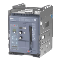
5.2 Dimension drawings
5.2.1 Fixed-mounted Circuit Breakers
The broken contour at the side depicts the 4-pole version.