Accessories
3.2 Preparatory and concluding installation steps for the installation of internal accessories
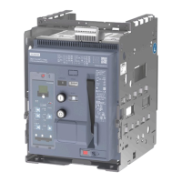
3WJ Air Circuit breakers
Operating Instructions, 12/2022, L1V30828903001-01
57
For interlocking
Reclosing lockout -F5 with tripped signaling contact -S11
Pushbutton "OPEN" (mechanical)
Pushbutton "CLOSED" (mechanical)
3.2 Preparatory and concluding installation steps for the installation
of internal accessories
This chapter describes the accessories available for the 3WJ Air Circuit Breaker. In some cases,
the front cover and secondary disconnect terminals have to be removed.
The different preparatory work for the installation of accessories is described in the following
section.
Before working on the 3WJ Air Circuit Breaker follow the instructions in chapter Safety
instructions (Page 7).
Hazardous voltage
Will cause death, serious personal injury or equipment damage.
Turn off and lock out all power supplying this equipment before working on this device.
Hazardous stored-energy spring mechanism
Will cause death, serious personal injury or equipment damage.
Before starting work, the device must be disconnected from the supply and protected
against reactivation.
Only carry out work on the device when the Circuit Breaker is switched off and the stored-
energy spring mechanism is discharged.
All devices must be installed and mounted by qualified authorized personnel only.
If a spring charging motor is configured, disconnect the control circuit to the spring charging
motor first, in order to prevent the stored
-energy spring from recharging.
If an undervoltage release is configured, control voltage must be applied to the UVR.
Preparatory work
1. Open the Circuit Breaker and discharge the stored-energy spring as described below
2. Rack the Circuit Breaker into maintenance position (disconnected postion) and remove it
from the guide frame (only withdrawable Circuit Breakers)
3. Remove the operator panel and the secondary disconnect terminals as shown below