03.06
1.1 System configuration
1-13
© Siemens AG, 2006. All rights reserved
SINUMERIK 840D Configuring Manual NCU (PHD) – 03.06 Edition
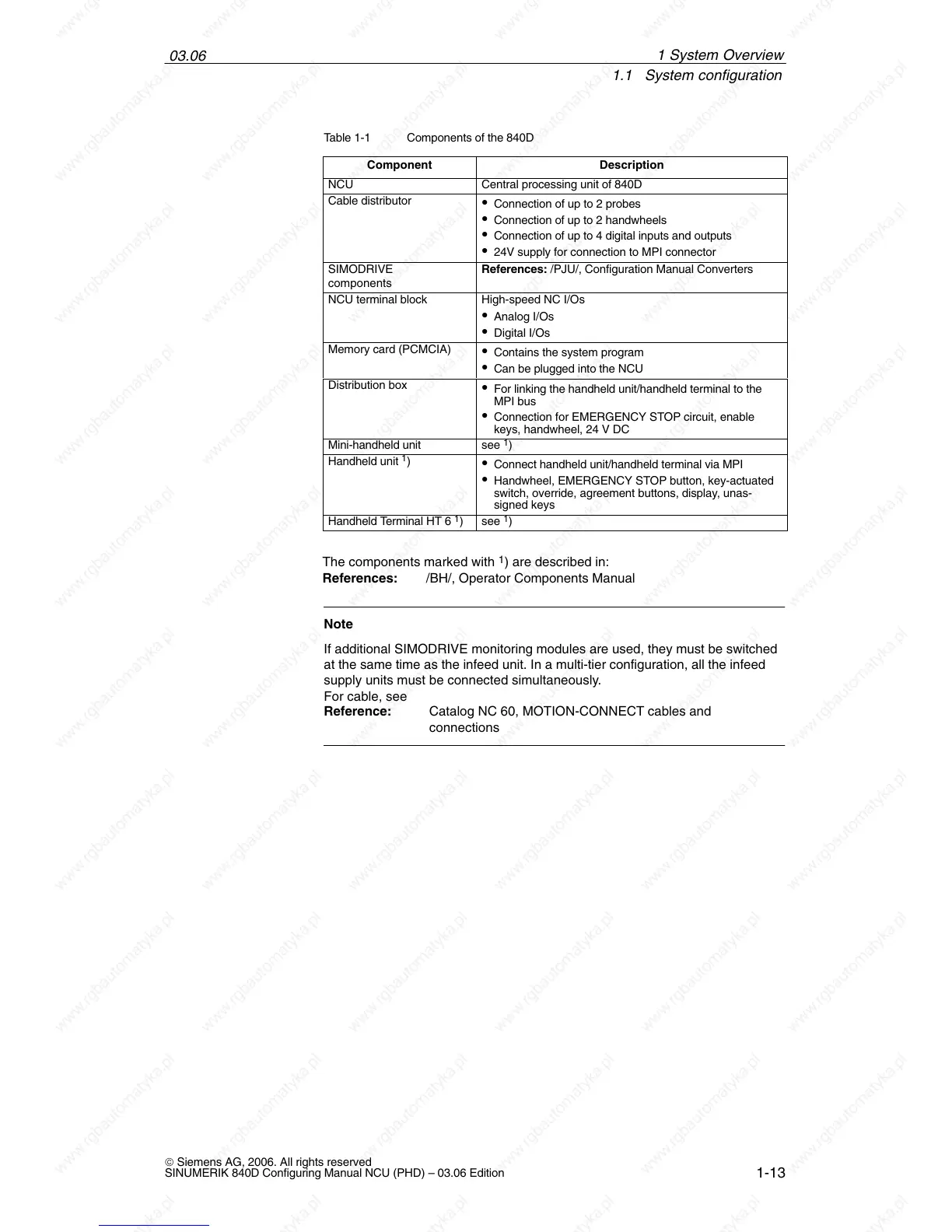
Table 1-1 Components of the 840D
Component
Description
NCU Central processing unit of 840D
Cable distributor
Connection of up to 2 probes
Connection of up to 2 handwheels
Connection of up to 4 digital inputs and outputs
24V supply for connection to MPI connector
SIMODRIVE
components
References: /PJU/, Configuration Manual Converters
NCU terminal block High-speed NC I/Os
Analog I/Os
Digital I/Os
Memory card (PCMCIA)
Contains the system program
Can be plugged into the NCU
Distribution box
For linking the handheld unit/handheld terminal to the
MPI bus
Connection for EMERGENCY STOP circuit, enable
keys, handwheel, 24 V DC
Mini-handheld unit see
1
)
Handheld unit
1
)
Connect handheld unit/handheld terminal via MPI
Handwheel, EMERGENCY STOP button, key-actuated
switch, override, agreement buttons, display, unas-
signed keys
Handheld Terminal HT 6
1
) see
1
)
The components marked with
1
) are described in:
References: /BH/, Operator Components Manual
Note
If additional SIMODRIVE monitoring modules are used, they must be switched
at the same time as the infeed unit. In a multi-tier configuration, all the infeed
supply units must be connected simultaneously.
For cable, see
Reference: Catalog NC 60, MOTION-CONNECT cables and
connections
1 S

 Loading...


