03.06
4.3 NCU module interfaces
4-54
© Siemens AG, 2006. All rights reserved
SINUMERIK 840D Configuring Manual NCU (PHD) – 03.06 Edition
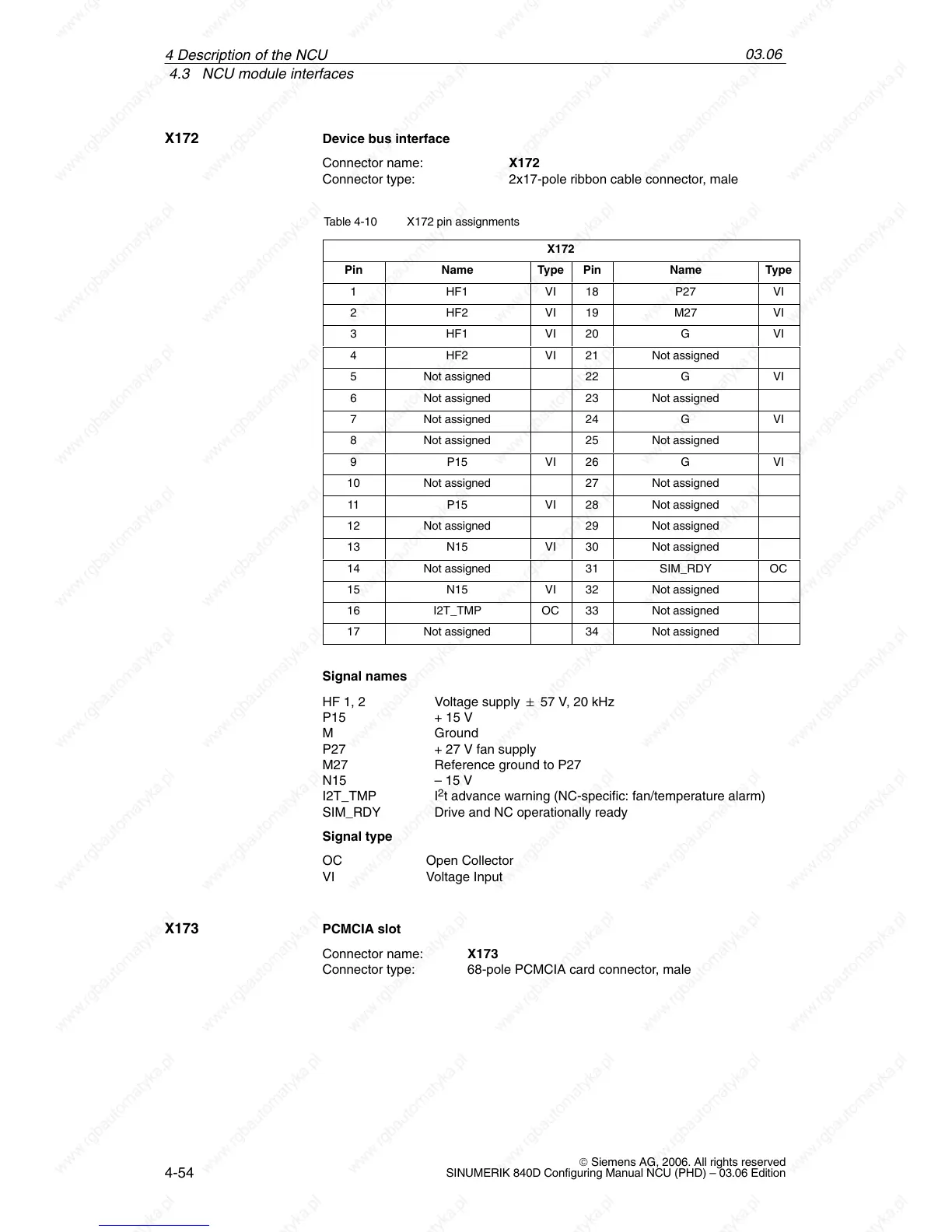
Device bus interface
Connector name: X172
Connector type: 2x17-pole ribbon cable connector, male
Table 4-10 X172 pin assignments
X172
Pin Name Type Pin Name Type
1 HF1 VI 18 P27 VI
2 HF2 VI 19 M27 VI
3 HF1 VI 20 G VI
4 HF2 VI 21 Not assigned
5 Not assigned 22 G VI
6 Not assigned 23 Not assigned
7 Not assigned 24 G VI
8 Not assigned 25 Not assigned
9 P15 VI 26 G VI
10 Not assigned 27 Not assigned
11 P15 VI 28 Not assigned
12 Not assigned 29 Not assigned
13 N15 VI 30 Not assigned
14 Not assigned 31 SIM_RDY OC
15 N15 VI 32 Not assigned
16 I2T_TMP OC 33 Not assigned
17 Not assigned 34 Not assigned
Signal names
HF 1, 2 Voltage supply " 57 V, 20 kHz
P15 + 15 V
M Ground
P27 + 27 V fan supply
M27 Reference ground to P27
N15 – 15 V
I2T_TMP I
2
t advance warning (NC-specific: fan/temperature alarm)
SIM_RDY Drive and NC operationally ready
Signal type
OC Open Collector
VI Voltage Input
PCMCIA slot
Connector name: X173
Connector type: 68-pole PCMCIA card connector, male
X172
X173
4 Descri

 Loading...


