03.06
4.3 NCU module interfaces
4-55
© Siemens AG, 2006. All rights reserved
SINUMERIK 840D Configuring Manual NCU (PHD) – 03.06 Edition
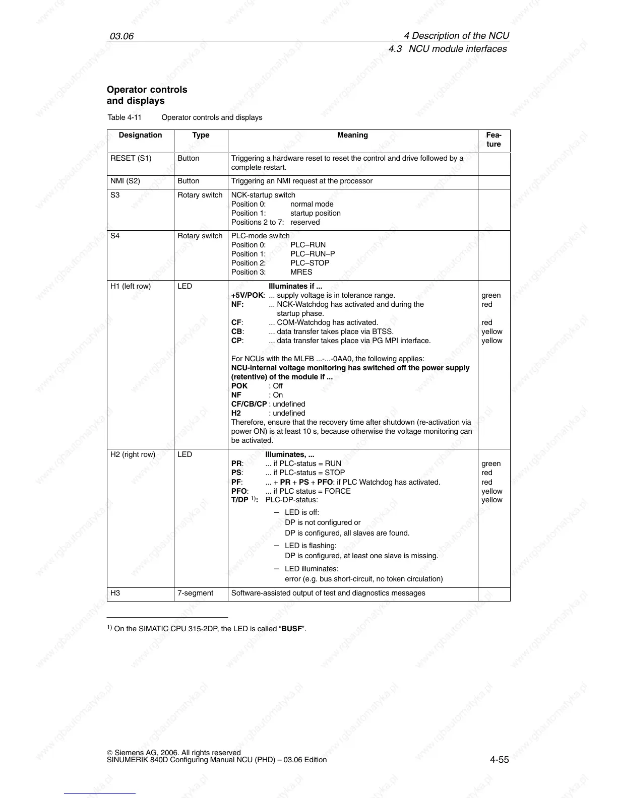
Table 4-11 Operator controls and displays
Designation
Type Meaning Fea-
ture
RESET (S1) Button Triggering a hardware reset to reset the control and drive followed by a
complete restart.
NMI (S2) Button Triggering an NMI request at the processor
S3 Rotary switch NCK-startup switch
Position 0: normal mode
Position 1: startup position
Positions 2 to 7: reserved
S4 Rotary switch PLC-mode switch
Position 0: PLC–RUN
Position 1: PLC–RUN–P
Position 2: PLC–STOP
Position 3: MRES
H1 (left row) LED Illuminates if ...
+5V/POK: ... supply voltage is in tolerance range.
NF: ... NCK-Watchdog has activated and during the
startup phase.
CF: ... COM-Watchdog has activated.
CB: ... data transfer takes place via BTSS.
CP: ... data transfer takes place via PG MPI interface.
For NCUs with the MLFB ...-...-0AA0, the following applies:
NCU-internal voltage monitoring has switched off the power supply
(retentive) of the module if ...
POK : Off
NF : On
CF/CB/CP : undefined
H2 : undefined
Therefore, ensure that the recovery time after shutdown (re-activation via
power ON) is at least 10 s, because otherwise the voltage monitoring can
be activated.
green
red
red
yellow
yellow
H2 (right row) LED Illuminates, ...
PR: ... if PLC-status = RUN
PS: ... if PLC-status = STOP
PF: ... + PR + PS + PFO: if PLC Watchdog has activated.
PFO: ... if PLC status = FORCE
T/DP
1)
: PLC-DP-status:
– LED is off:
DP is not configured or
DP is configured, all slaves are found.
– LED is flashing:
DP is configured, at least one slave is missing.
– LED illuminates:
error (e.g. bus short-circuit, no token circulation)
green
red
red
yellow
yellow
H3 7-segment Software-assisted output of test and diagnostics messages
1)
On the SIMATIC CPU 315-2DP, the LED is called “BUSF”.
Operator controls
and displays
4 Descri

 Loading...


