2.5 Distance Protection
143
7SD5 Manual
C53000-G1176-C169-1
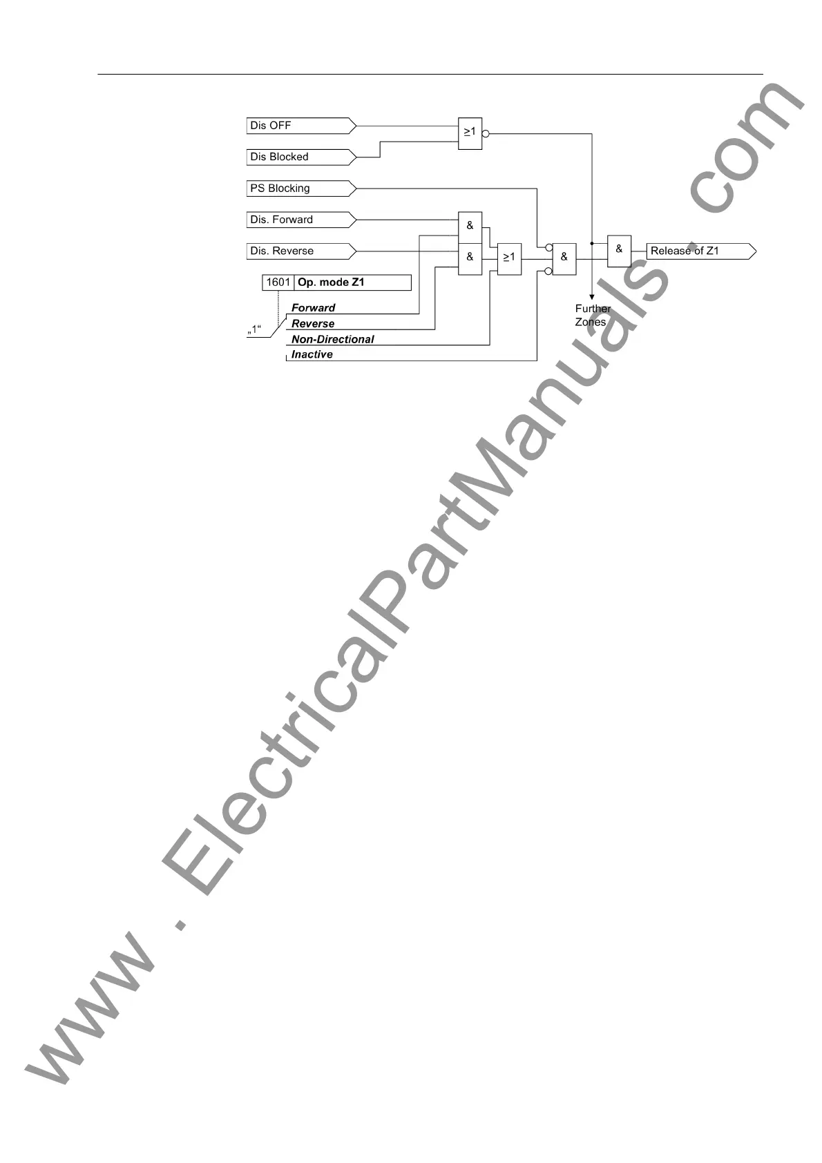
Figure 2-47 Release logic for a zone (example for Z1)
In total, the following zones are available:
Independent zones:
• 1st zone (fast tripping zone) Z1 with X(Z1); R(Z1) Ø-Ø, RE(Z1) Ø-E; delayable
with T1-1phase or T1-multi-phase,
• 2nd zone (backup zone) Z2 with X(Z2); R(Z2) Ø-Ø, RE(Z2) Ø-E; may be
delayed by T2-1phase or T2-multi-phase,
• 3rd zone (backup zone) Z3 with X(Z3); R(Z3) Ø-Ø, RE(Z3) Ø-E; may be
delayed by T3 DELAY,
• 4th zone (backup zone) Z4 with X(Z4); R(Z4) Ø-Ø, RE(Z4) Ø-E; may be
delayed by T4 DELAY,
• 5th zone (backup zone) Z5 with X(Z5)+ (forward) and X(Z5)- (reverse); R(Z5)
Ø-Ø, RE(Z5) Ø-E, delayable with T5 DELAY.
Dependent (controlled) zone:
• Overreaching zone Z1B with X(Z1B); R(Z1B) Ø-Ø, RE(Z1B) Ø-E; may be
delayed by T1B-1phase or T1B-multi-phase.
2.5.2.2 Setting Notes
Grading Coordina-
tion Chart
It is recommended to initially create a grading coordination chart for the entire galvan-
ically interconnected system. This diagram should reflect the line lengths with their
primary reactances X in Ω/km. For the reach of the distance zones, the reactances X
are the deciding quantity.
The first zone Z1 is usually set to cover 85 % of the protected line without any trip time
delay (i.e. T1 = 0.00 s). The protection clears faults in this range without additional
time delay, i.e. the tripping time is the relay basic operating time.
The tripping time of the higher zones is sequentially increased by one time grading in-
terval. The grading margin must take into account the circuit breaker operating time
including the spread of this time, the resetting time of the protection equipment as well
as the spread of the protection delay timers. Typical values are 0.2 s to 0.4 s. The
reach is selected to cover up to approximately 80% of the zone with the same set time
delay on the shortest neighbouring feeder.
www . ElectricalPartManuals . com
 Loading...


