2.23 Function Control and Circuit Breaker Test
409
7SD5 Manual
C53000-G1176-C169-1
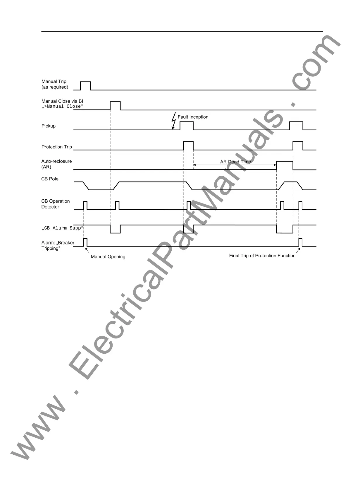
Figure 2-181 shows time diagrams for manual trip and close as well as for short-circuit
tripping with a single, failed automatic reclosure cycle.
Figure 2-181 Breaker tripping alarm suppression — sequence examples
2.23.2 Circuit Breaker Test
The universal line protection 7SD5 allows an easy check of the trip circuits and the
circuit breakers.
2.23.2.1 Functional Description
The test programs as shown in Table 2-19 are available. The single-pole tests are nat-
urally only available if the device at hand allows for single-pole tripping.
The output alarms mentioned must be allocated to the relevant command relays that
are used for controlling the circuit breaker coils.
The test is started using the operator panel on the front of the device or using the PC
with DIGSI
®
. The procedure is described in detail in the SIPROTEC
®
4 System De-
scription. Figure 2-182 shows the chronological sequence of one TRIP–CLOSE test
cycle. The set times are those stated in Section 2.1.2.1 for „Trip Command Duration“
and „Circuit Breaker Test“.
Where the circuit breaker auxiliary contacts indicate the status of the circuit breaker or
of its poles to the device via binary inputs, the test cycle can only be initiated if the
circuit breaker is closed.
www . ElectricalPartManuals . com
 Loading...


