2.3 Differential Protection
89
7SD5 Manual
C53000-G1176-C169-1
2.3 Differential Protection
The differential protection represents the main protection function of the device. It is
based on current comparison. For this, one device must be installed at each end of the
zone to be protected. The devices exchange their measured quantities via communi-
cations links and compare the received currents with their own. In case of an internal
fault the allocated circuit breaker is tripped.
Depending on the ordered model, the 7SD5 is designed for protected objects with up
to 6 ends. Thus, with exception of normal lines, three and multi-branch lines can also
be protected with or without connected transformers in block as well as small busbars.
The protected zone is selectively limited by the CTs at its ends.
Differential protection can be configured in parallel to distance protection (Main2), or
as sole protection function (refer also to Section 2.1.1.3).
2.3.1 Functional Description
Basic Principle
with Two Ends
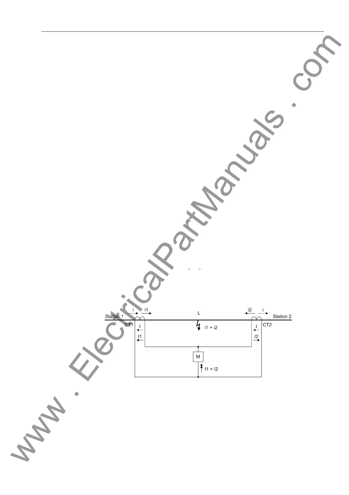
Differential protection is based on current comparison. It makes use of the fact that
e.g. a line section L (Figure 2-14) carries always the same current i (dashed line) at its
two ends in healthy operation. This current flows into one side of the considered zone
and leaves it again on the other side. A difference in current is a clear indication of a
fault within this line section. If the actual current transformation ratios are the same,
the secondary windings of the current transformers CT1 and CT2 at the line ends can
be connected to form a closed electric circuit with a secondary current I; a measuring
element M which is connected to the electrical balance point remains at zero current
in healthy operation.
When a fault occurs in the zone limited by the transformers, a current i
1
+ i
2
which is
proportional to the fault currents I
1
+ I
2
flowing in from both sides is fed to the measur-
ing element. As a result, the simple circuit shown in Figure 2-14 ensures a reliable trip-
ping of the protection if the fault current flowing into the protected zone during a fault
is high enough for the measuring element M to respond.
Figure 2-14 Basic principle of the differential protection for a line with two ends
Basic Principle with
Multiple Ends
For lines with three or more ends or for busbars, the principle of differential protection
is extended in that the total sum of all currents flowing into the protected object is zero
in healthy operation, whereas in case of a fault the total sum is equal to the fault
current (see Figure 2-15 as an example for four ends).
www . ElectricalPartManuals . com
 Loading...


