2 Functions
380
7SD5 Manual
C53000-G1176-C169-1
Measured Value Ac-
quisition Voltages
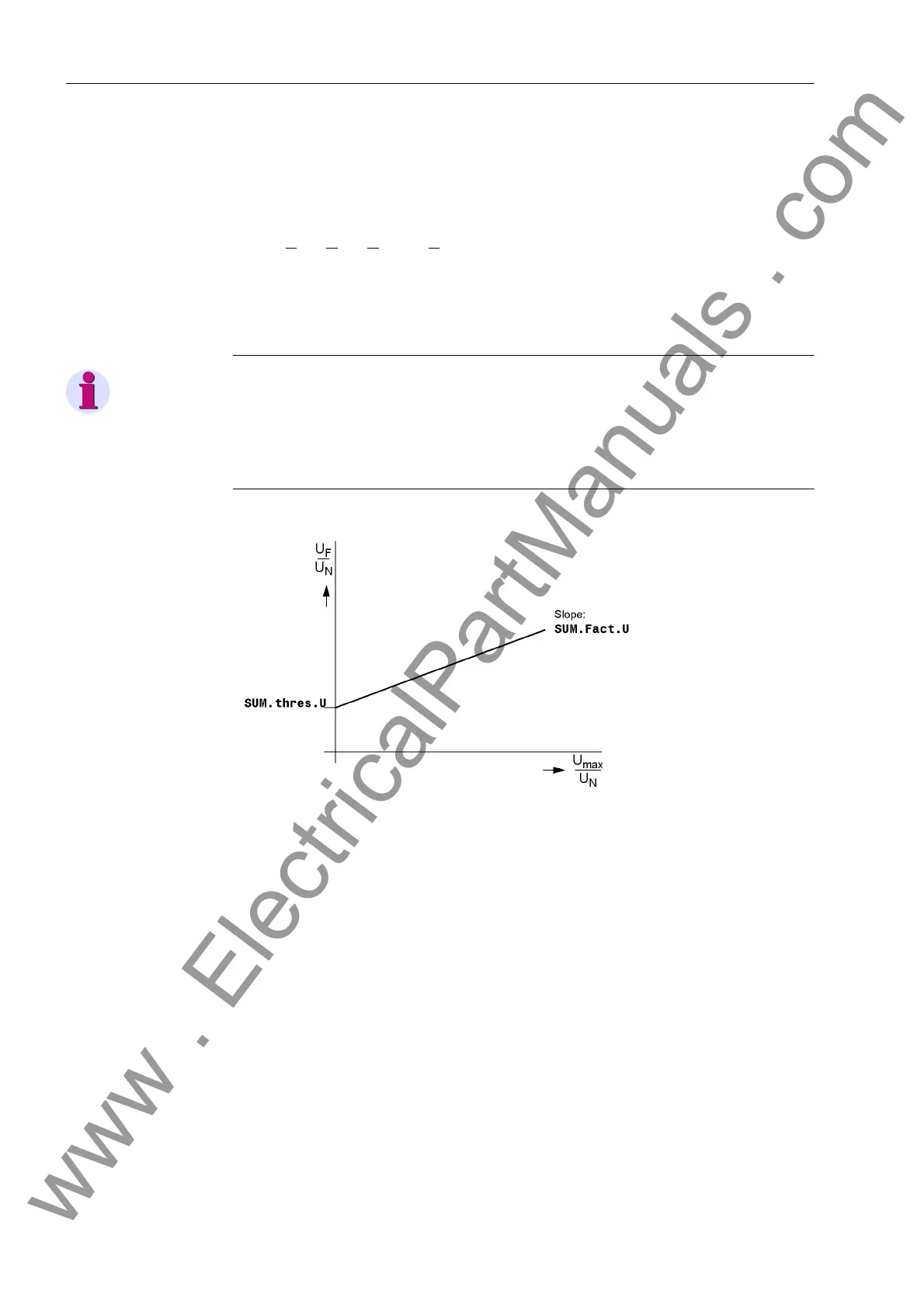
Four measuring inputs are available in the voltage path: three for phase–earth voltag-
es as well as one input for the displacement voltage (e-n voltage of an open delta con-
nection) or a busbar voltage. If the displacement voltage is connected to the device,
the sum of the three digitized phase voltages must equal three times the zero se-
quence voltage. Errors in the voltage transformer circuits are detected when
U
F
= |U
L1
+ U
L2
+ U
L3
+ k
U
·U
EN
| > 25 V.
Factor k
U
considers the transformation ratio differences between the displacement
voltage input and the phase voltage inputs (parameter Uph / Udelta).
This malfunction is reported as „Fail Σ U Ph-E“.
Note
Voltage sum monitoring can operate properly only when an externally formed open
delta voltage is connected to the residual voltage input of the relay.
Voltage sum monitoring can operate properly only if the adaptation factor Uph /
Udelta at address 211 has been correctly configured (see Section 2.1.2.1).
Figure 2-163 Voltage sum monitoring
2.22.1.2 Software Monitoring
Watchdog For continuous monitoring of the program sequences, a time monitor is provided in the
hardware (watchdog for hardware) that expires upon failure of the processor or an in-
ternal program, and causes a reset of the processor system with complete restart.
An additional software watchdog ensures that malfunctions during the processing of
programs are discovered. This also initiates a restart of the processor system.
To the extent such a malfunction is not cleared by the restart, an additional restart
attempt is begun. Following three failed restarts within 30 s the protection takes itself
out of service and the red LED „ERROR“ is illuminated. The device ready relay resets
and alarms the device failure state with its normally closed contact („life contact“).
www . ElectricalPartManuals . com
 Loading...


