2.22 Monitoring Functions
379
7SD5 Manual
C53000-G1176-C169-1
Sampling
Frequency
The sampling frequency and the synchronism between the ADCs (analog-to-digital
converters) is continuously monitored. If deviations cannot be corrected by another
synchronization, the device sets itself out of operation and the red LED „Blocked“
lights up. The Device OK relay drops off and signals the malfunction by its „life con-
tact“.
Measurement Value
Acquisition – Cur-
rents
Up to four input currents are measured by the device. If the three phase currents and
the earth fault current from the current transformer starpoint or a separated earth
current transformer of the line to be protected are connected to the device, their digi-
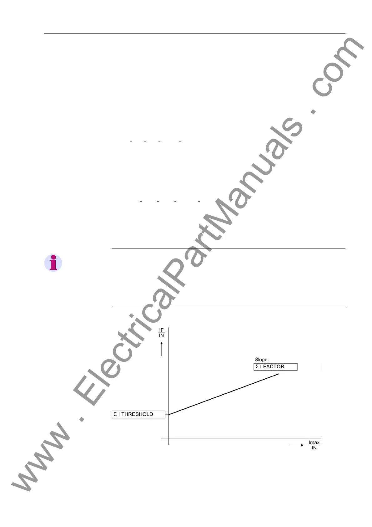
tized sum must be zero. Faults in the current circuit are recognized if
I
F
= |I
L1
+ I
L2
+ I
L3
+ k
I
·I
E
| > ΣI THRESHOLD·I
N
+ ΣI FACTOR·Σ | I |
Factor k
I
(address I4/Iph CT) takes into account a possible different ratio of a sep-
arate I
E
-transformer (e.g. cable core balance current transformer). ΣI THRESHOLD
and ΣI FACTOR are setting parameters. The component ΣI FACTOR·Σ | I | takes into
account the allowable current proportional ratio errors of the input transducers which
are particularly prevalent during large fault currents (Figure 2-162). Σ | I | is the sum of
all currents:
Σ | I | = |I
L1
| + |I
L2
| + |I
L3
| + |k
I
·I
E
|
As soon as a summation current fault is detected after or before a system disturbance,
the differential protection is blocked. This malfunction is signalled as „Failure Σi“
(No. 289). In order to avoid a blocking due to transformation errors (saturation) in case
of high fault currents, this monitoring function is not effective during a system fault.
Note
Current sum monitoring can operate properly only when the residual current of the
protected line is fed to the fourth current input (II
4
) of the relay. The I
4
transformer must
have been configured as In prot. line via parameter I4 transformer (220).
Also, the fourth current input must have the ratings of a normal I
4
transformer. With a
sensitive transformer type, current sum monitoring is not activated.
Figure 2-162 Current sum monitoring
www . ElectricalPartManuals . com
 Loading...


