4.1 General
519
7SD5 Manual
C53000-G1176-C169-1
4.1 General
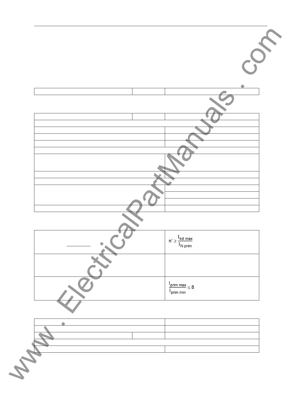
4.1.1 Analog Inputs
Current Inputs
Requirements for current transformers
Voltage inputs
Nominal frequency f
N
50 Hz or 60 Hz (adjustable)
Nominal current I
N
1 A or 5 A
Power Consumption per Phase and Earth Path
- at I
N
= 1 A Approx. 0.05 VA
- at I
N
= 5 A Approx. 0.3 VA
- for sensitive earth fault detection at 1A Approx. 0.05 VA
Current Overload Capability per Current Input
- thermal (rms) 100 · I
N
for 1 s
30 · I
N
for 10 s
4 · I
N
continuous
- dynamic (pulse current) 250 · I
N
(half-cycle)
Current Overload Capability for Sensitive Earth Current Input
- thermal (rms) 300 A for 1 s
100 A for 10 s
15 A continuous
- dynamic (pulse current) 750 A (half-cycle)
1st Condition:
For a maximum fault current the current transformers must not be
saturated under steady-stateconditions
2nd Condition:
The operational accuracy limit factor n' must be at least 30 or a non-
saturated period of t'
AL
of at least
1
/
4
AC cycle after fault inception
must be ensured
n' ≥ 30
or
t'
AL
≥
1
/
4
cycle
3 rd Condition:
Maximum ratio between primary currents of current transformers at
the ends of the protected object
Nominal voltage U
N
80 V to 125 V (adjustable)
Measuring range 0 V to 218.5 V (rms)
Power consumption At 100 V ≤ 0.1 VA
Voltage overload capability per phase
- thermal (rms) 230 V continuous
www . ElectricalPartManuals . com
 Loading...


