2.8 Earth Fault Protection in Earthed Systems (optional)
215
7SD5 Manual
C53000-G1176-C169-1
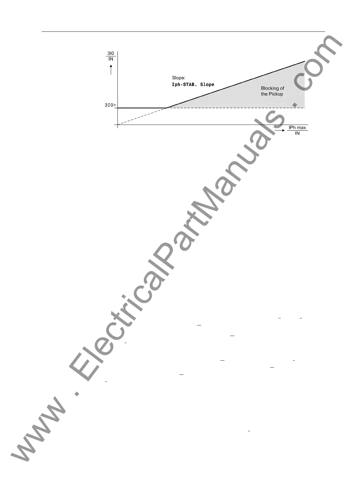
Figure 2-93 Phase current stabilization
Inrush Stabilization If the device is connected to a transformer feeder, large inrush currents can be expect-
ed when the transformer is energized; if the transformer starpoint is earthed, also in
the zero sequence path. The inrush current may be a multiple of the rated current and
flow for several tens of milliseconds up to several minutes.
Although the fundamental current is evaluated by filtering of the measured current, an
incorrect pickup during energization of the transformer may result if very short delay
times are set. In the rush current there is a substantial portion of fundamental current
depending on the type and size of the transformer that is being energized.
The inrush stabilization blocks tripping of all those stages for which it has been acti-
vated, for as long as the rush current is recognized.
The inrush current contains a relatively large second harmonic component (twice the
nominal frequency) which is nearly absent during a fault current. Numerical filters that
carry out a Fourier analysis of the current are used for the frequency analysis. As soon
as the harmonic content is greater than the set value (2nd InrushRest), the affect-
ed stage is blocked.
Inrush blocking is not effective below a certain current threshold. This threshold is
22 mA on the secondary side for devices with sensitive earth current transformer and
0.41 I
N
for devices with normal earth current transformer.
Direction Determi-
nation with Zero-
Sequence System
The direction determination is carried out with the measured current I
E
(= –3·I
0
), which
is compared to a reference voltage U
P
.
The voltage required for direction determination U
P
may be derived of the starpoint
current I
Y
of an earthed transformer (source transformer), provided that the transform-
er is available.
Moreover, both the zero sequence voltage 3·U
0
and the starpoint current I
Y
of a trans-
former can be used for measurement. The reference magnitude U
P
then is the sum of
the zero sequence voltage 3·U
0
and a value which is proportional to reference current
I
Y
. This value is about 20 V for rated current (Figure 2-94).
The directional polarization using the transformer starpoint current is independent of
voltage transformers and therefore also functions reliably during a fault in the voltage
transformer secondary circuit. It is, however, a requirement that not all, but at least a
substantial amount of the earth fault current flows via the transformer, the starpoint
current of which is measured.
For the determination of direction, a minimum current 3I
0
and a minimum displace-
ment voltage which can be set as 3U0> is required. If the displacement voltage is too
www . ElectricalPartManuals . com
 Loading...


