2 Functions
384
7SD5 Manual
C53000-G1176-C169-1
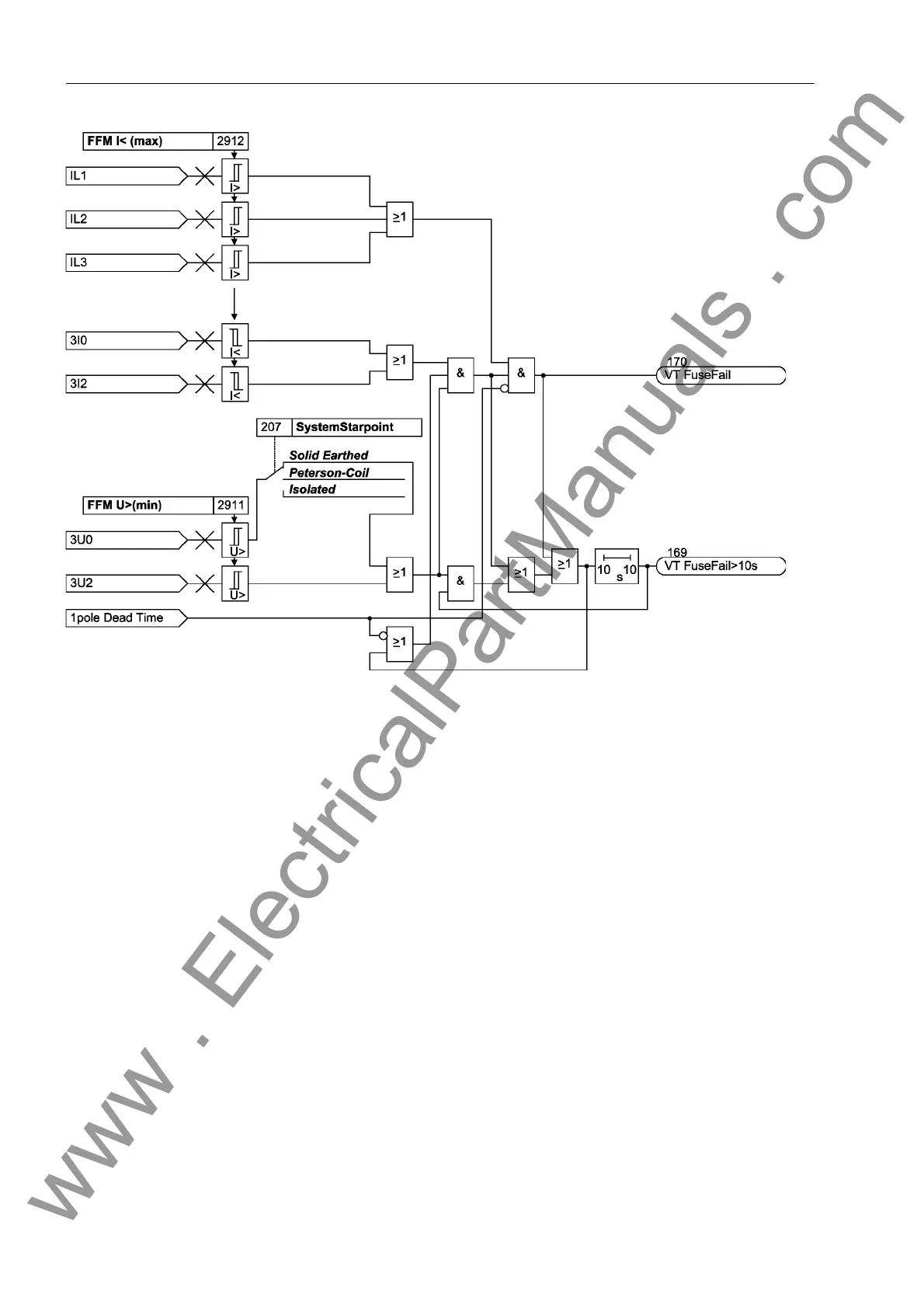
Figure 2-166 Logic diagram of the fuse failure monitor with zero and negative sequence system
Three-Phase Mea-
suring Voltage
Failure "Fuse
Fail ure Monit o r"
A three-phase failure of the secondary measured voltage can be distinguished from
an actual system fault by the fact that the currents have no significant change in the
event of a failure in the secondary measured voltage. For this reason, the sampled
current values are routed to a buffer, so that the difference between the present and
stored current values can be analysed to recognize the magnitude of the current dif-
ferential (current differential criterion). A three-pole voltage failure is detected if
• All three phase-to-earth voltages are smaller than the threshold FFM U<max
(3ph),
• The current differential in all three phases is smaller than the threshold FFM
Idelta (3p).
• All three phase current amplitudes are greater than the minimum current Iph> for
impedance measurement by the distance protection.
If no stored current values are present (yet), the current magnitude criterion is resorted
to. A three-pole system voltage failure is detected in this case if
• All three phase-to-earth voltages are smaller than the threshold FFM U<max
(3ph),
• All three phase current amplitudes are smaller than the minimum current Iph> for
impedance measurement by the distance protection, and
• All three phase current amplitudes are greater than a fixed set noise threshold
(40mA).
www . ElectricalPartManuals . com
 Loading...


