2.1 General
61
7SD5 Manual
C53000-G1176-C169-1
Earth Impedance
(Residual) Com-
pensation with
Scalar Factors
R
E
/R
L
and X
E
/X
L
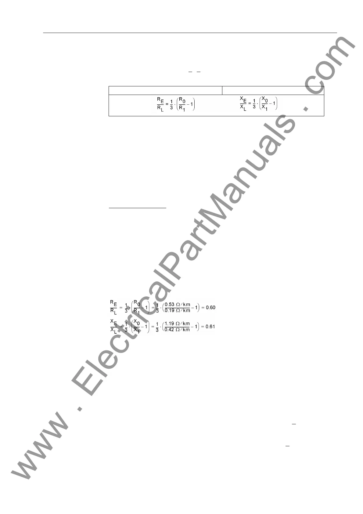
When entering the resistance ratio R
E
/R
L
and the reactance ratio X
E
/X
L
the addresses
1116 to 1119 apply. They are calculated separately, and do not correspond to the real
and imaginary components of Z
E
/Z
L
. A computation with complex numbers is therefore
not necessary! The ratios are obtained from system data using the following formulas:
Where
R
0
= Zero sequence resistance of the line
X
0
= Zero sequence reactance of the line
R
1
= Positive sequence resistance of the line
X
1
= Positive sequence reactance of the line
These values may either apply to the entire line length or be based on a per unit of line
length, as the quotients are independent of length. Furthermore it makes no difference
if the quotients are calculated with primary or secondary values.
Calculation Example:
110 kV overhead line 150 mm
2
with the following data:
R
1
/s = 0.19 Ω/km positive sequence impedance
X
1
/s = 0.42 Ω/km positive sequence impedance
R
0
/s = 0.53 Ω/km zero sequence impedance
X
0
/s = 1.19 Ω/km zero sequence impedance
(where s = line length)
For earth impedance ratios, the following emerge:
The earth impedance (residual) compensation factor setting for the first zone Z1 may
be different from that of the remaining zones of the distance protection. This allows the
setting of the exact values for the protected line, while at the same time the setting for
the back-up zones may be a close approximation even when the following lines have
substantially different earth impedance ratios (e.g. cable after an overhead line). Ac-
cordingly, the settings for the address 1116 RE/RL(Z1)and 1117 XE/XL(Z1) are
determined with the data of the protected line while the addresses 1118
RE/RL(Z1B...Z5) and 1119 XE/XL(Z1B...Z5) apply to the remaining zones
Z1B and Z2 up to Z5 (as seen from the relay location).
Earth Impedance
(Residual) Com-
pensation with
Magnitude and
Angle (K
0
–Factor)
When the complex earth impedance (residual) compensation factor K
0
is set, the ad-
dresses 1120 to 1123 apply. In this case it is important that the line angle is set cor-
rectly (address 1105, see margin heading „General Line Data“) as the device needs
the line angle to calculate the compensation components from the K
0
. These earth im-
Resistance ratio: Reactance ratio:
www . ElectricalPartManuals . com
 Loading...


