A Appendix
620
7SD5 Manual
C53000-G1176-C169-1
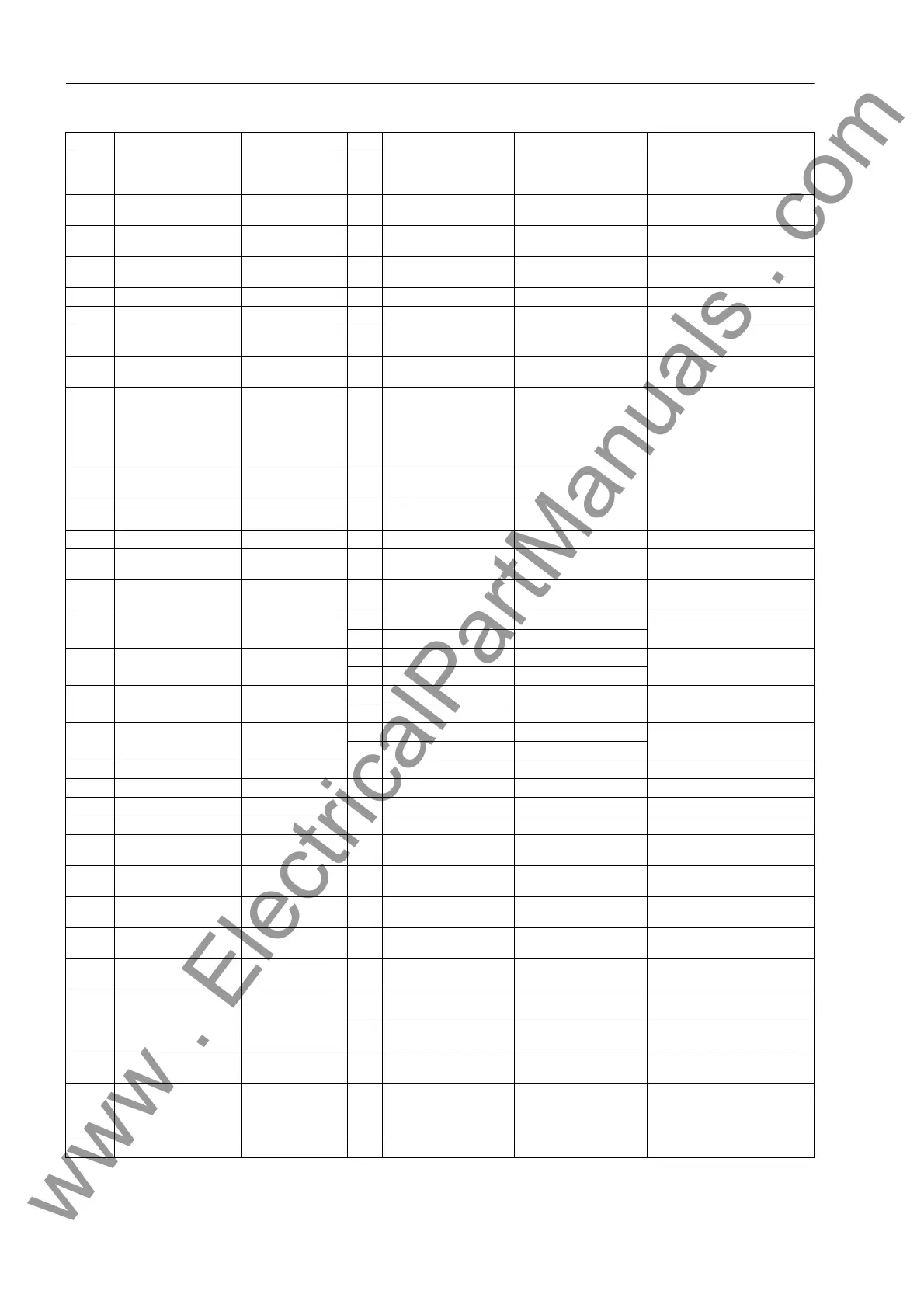
402A WAVEFORMTRIGGER Osc. Fault Rec. Save w. Pickup
Save w. TRIP
Start w. TRIP
Save w. Pickup Waveform Capture
403A WAVEFORM DATA Osc. Fault Rec. Fault event
Pow.Sys.Flt.
Fault event Scope of Waveform Data
410 MAX. LENGTH Osc. Fault Rec. 0.30 .. 5.00 sec 2.00 sec Max. length of a Waveform
Capture Record
411 PRE. TRIG. TIME Osc. Fault Rec. 0.05 .. 0.50 sec 0.25 sec Captured Waveform Prior to
Trigger
412 POST REC. TIME Osc. Fault Rec. 0.05 .. 0.50 sec 0.10 sec Captured Waveform after Event
415 BinIn CAPT.TIME Osc. Fault Rec. 0.10 .. 5.00 sec; ∞ 0.50 sec Capture Time via Binary Input
610 FltDisp.LED/LCD Device Target on PU
Target on TRIP
Target on PU Fault Display on LED / LCD
615 Spont. FltDisp. Device NO
YES
NO Spontaneous display of flt.an-
nunciations
640 Start image DD Device image 1
image 2
image 3
image 4
image 5
image 6
image 1 Start image Default Display
1103 FullScaleVolt. P.System Data 2 0.4 .. 1200.0 kV 400.0 kV Measurement: Full Scale Voltage
(100%)
1104 FullScaleCurr. P.System Data 2 10 .. 5000 A 1000 A Measurement: Full Scale Current
(100%)
1105 Line Angle P.System Data 2 30 .. 89 ° 85 ° Line Angle
1106 OPERATION POWER P.System Data 2 0.2 .. 5000.0 MVA 692.8 MVA Operational power of protection
zone
1107 P,Q sign P.System Data 2 not reversed
reversed
not reversed P,Q operational measured values
sign
1111 x' P.System Data 2 1A 0. 0050 .. 9.5000 Ω/km 0.1500 Ω/km x' - Line Reactance per length
unit
5A 0.0010 .. 1.9000 Ω/km 0.0300 Ω/km
1111 x' P.System Data 2 1A 0. 0050 .. 15.0000 Ω/mi 0.2420 Ω/mi x' - Line Reactance per length
unit
5A 0.0010 .. 3.0000 Ω/mi 0.0484 Ω/mi
1112 c' P.System Data 2 1A 0.000 .. 100.000 µF/km 0.010 µF/km c' - capacit. per unit line len.
µF/km
5A 0.000 .. 500.000 µF/km 0.050 µF/km
1112 c' P.System Data 2 1A 0.000 .. 160.000 µF/mi 0.016 µF/mi c' - capacit. per unit line len.
µF/mile
5A 0.000 .. 800.000 µF/mi 0.080 µF/mi
1113 Line Length P.System Data 2 0.1 .. 1000.0 km 100.0 km Line Length
1113 Line Length P.System Data 2 0.1 .. 650.0 Miles 62.1 Miles Line Length
1114 Tot.Line Length P.System Data 2 0.1 .. 1000.0 km 100.0 km Total Line Length
1114 Tot.Line Length P.System Data 2 0.1 .. 650.0 Miles 62.1 Miles Total Line Length
1116 RE/RL(Z1) P.System Data 2 -0.33 .. 7.00 1.00 Zero seq. comp. factor RE/RL for
Z1
1117 XE/XL(Z1) P.System Data 2 -0.33 .. 7.00 1.00 Zero seq. comp. factor XE/XL for
Z1
1118 RE/RL(Z1B...Z5) P.System Data 2 -0.33 .. 7.00 1.00 Zero seq. comp.factor RE/RL for
Z1B...Z5
1119 XE/XL(Z1B...Z5) P.System Data 2 -0.33 .. 7.00 1.00 Zero seq. comp.factor XE/XL for
Z1B...Z5
1120 K0 (Z1) P.System Data 2 0.000 .. 4.000 1.000 Zero seq. comp. factor K0 for
zone Z1
1121 Angle K0(Z1) P.System Data 2 -135.00 .. 135.00 ° 0.00 ° Zero seq. comp. angle for zone
Z1
1122 K0 (> Z1) P.System Data 2 0.000 .. 4.000 1.000 Zero seq.comp.factor K0,higher
zones >Z1
1123 AngleI K0(> Z1) P.System Data 2 -135.00 .. 135.00 ° 0.00 ° Zero seq. comp. angle, higher
zones >Z1
1124 center phase P.System Data 2 unknown/sym.
Phase 1
Phase 2
Phase 3
unknown/sym. center phase of feeder
1125 C0/C1 P.System Data 2 0.01 .. 10.00 0.75 Compensation factor C0/C1
Addr. Parameter Function C Setting Options Default Setting Comments
www . ElectricalPartManuals . com

 Loading...


