2.1 General
63
7SD5 Manual
C53000-G1176-C169-1
The magnitude and angle of the earth impedance (residual) compensation factors
setting for the first zone Z1 and the remaining zones of the distance protection may be
different. This allows the setting of the exact values for the protected line, while at the
same time the setting for the back-up zones may be a close approximation even when
the following lines have substantially different earth impedance factors (e.g. cable after
an overhead line). Accordingly, the settings for the address 1120 K0 (Z1)and 1121
Angle K0(Z1) are determined with the data of the protected line while the addresses
1122 K0 (> Z1) and 1123 AngleI K0(> Z1) apply to the remaining zones Z1B
and Z2 up to Z5 (as seen from the relay mounting location).
Note
If a combination of values is set which is not recognized by the device, it operates with
preset values K
0
= 1 · e
0°
. The information „Dis.ErrorK0(Z1)“ (No. 3654) or
„DisErrorK0(>Z1)“ (No. 3655) appears in the event logs.
Level Arrangement The center phase of a level arrangement is determined in address 1124 center
phase. The compensation factor parameters C0/C1 (address 1125) and center
phase are reserved for the double-ended fault locator. They are used for configuration
of a line with different sections (e.g. overhead line-cable). Refer to Section 2.19 for
more details.
Parallel Line Mutual
Impedance
(optional)
If the device is applied to a double circuit line (parallel lines) and parallel line compen-
sation for the distance and/or fault location function is used, the mutual coupling of the
two lines must be considered. A prerequisite for this is that the earth (residual) current
of the parallel line has been connected to the measuring input I
4
of the device and that
this was configured with the power system data (Section 2.1.2.1) by setting the appro-
priate parameters.
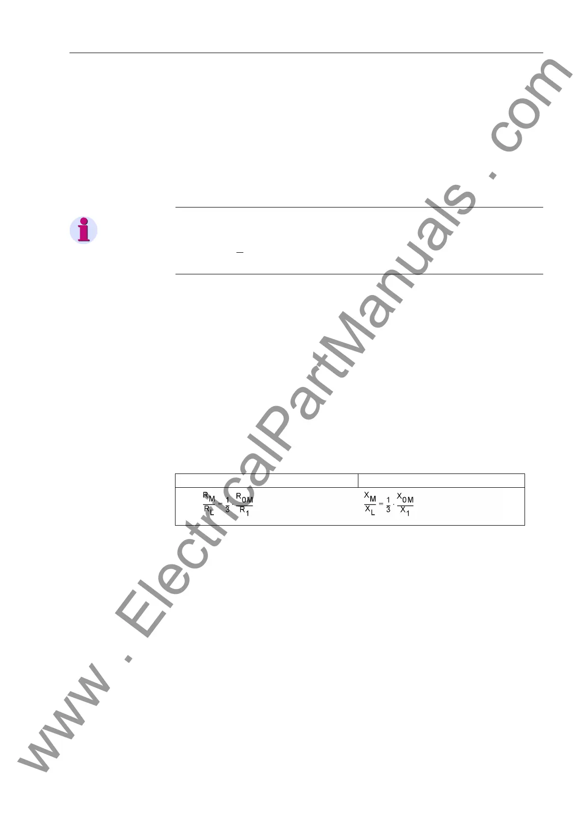
The coupling factors may be determined using the following equations:
where
R
0M
= Mutual zero sequence resistance (coupling resistance) of the line
X
0M
= Mutual zero sequence reactance (coupling reactance) of the line
R
1
= Positive sequence resistance of the line
X
1
= Positive sequence reactance of the line
These values may either apply to the entire double circuit line length or be based on
a per unit of line length, as the quotient is independent of length. Furthermore it makes
no difference whether the quotients are calculated with primary, or secondary values.
These setting values only apply to the protected line and are entered in the addresses
1126 RM/RL ParalLine and 1127 XM/XL ParalLine.
For earth faults on the protected feeder there is in theory no additional distance pro-
tection or fault locator measuring error when the parallel line compensation is used.
The setting in address 1128 RATIO Par. Comp is therefore only relevant for earth
faults outside the protected feeder. It provides the current ratio I
E
/I
EP
for the earth
Resistance ratio: Reactance ratio:
www . ElectricalPartManuals . com
 Loading...


