2.3 Restricted Earth Fault Protection
145
7UT613/63x Manual
C53000-G1176-C160-2
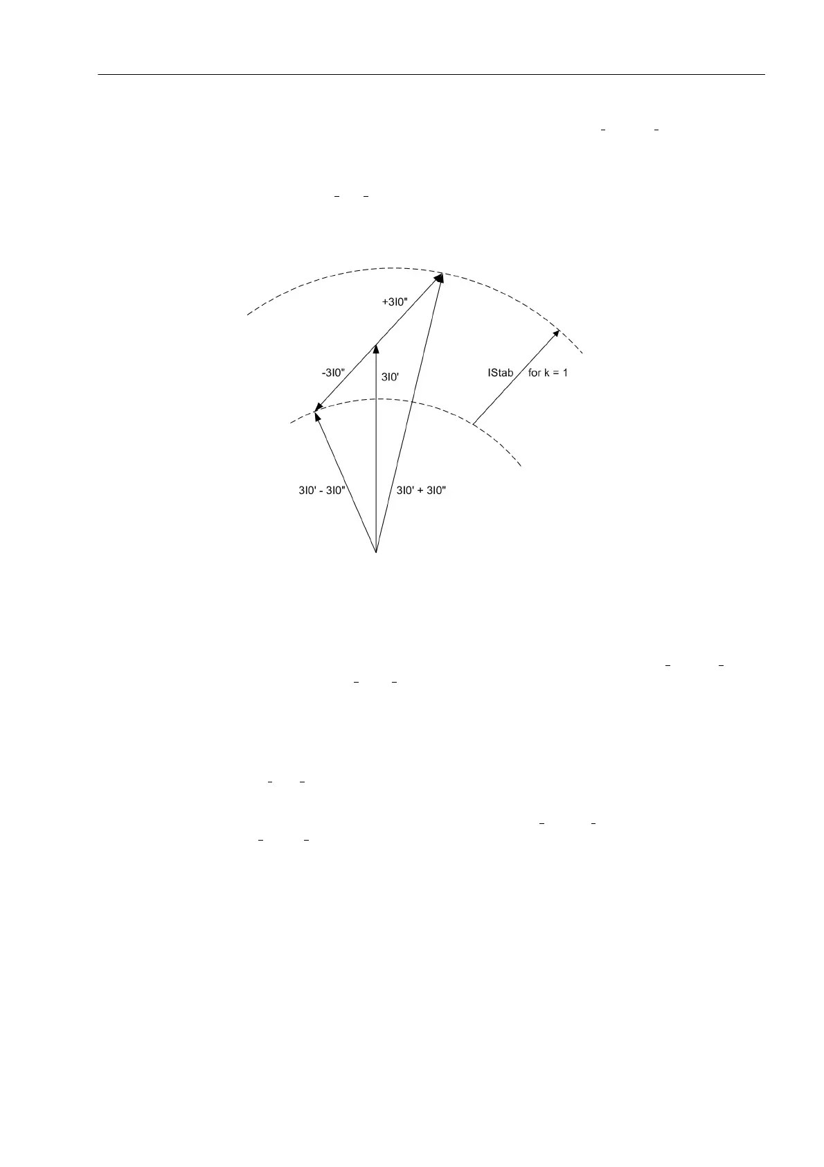
It was assumed in the above examples that the currents 3I
0
" and 3I
0
' are in counter-
phase for external earth faults which is only true for the primary measured quantities.
Current transformer saturation may cause phase shifting between the fundamental
waves of the secondary currents which reduces the restraint quantity. If the phase dis-
placement ϕ(3I
0
"; 3I
0
') = 90° then the restraint quantity is zero. This corresponds to the
conventional method of direction determination by use of the vectorial sum and differ-
ence comparison.
Figure 2-61 Phasor diagram of the restraint quantity during external fault
The restraint quantity can be influenced by means of a factor k. This factor has a
certain relationship to the limit angle ϕ
Limit
.
This limit angle determines for which phase displacement between 3I
0
" and 3I
0
' the
pickup value for 3I
0
"=3I
0
' grows to ∞, i.e. no pickup occurs. In 7UT613/63x k is equal
to 4.
The restraint quantity I
stab
in the above example a) is quadrupled once more; it
becomes thus 8 times the tripping effect quantity I
from
.
The limit angle is ϕ
Limit
= 100°. That means no trip is possible for phase displacement
ϕ(3I
0
";°3I
0
')| ≥ +100°.
Figure 2-62 shows the operating characteristics of the restricted earth fault protection
dependent of the phase displacement between 3I
0
" and 3I
0
', for a constant infeed ratio
|3I
0
"| = |3I
0
'|.
 Loading...


