A.4 Current Transformer Requirements
539
7UT613/63x Manual
C53000-G1176-C160-2
A.4 Current Transformer Requirements
Formula symbols/terms used (in accordance with IEC 60044-6, as defined)
The transient rated dimensioning factor K
td
depends on the device version and the
primary time constant T
p
. For the devices 7UT613/63x with a required saturation-free
time of only
1
/
4
period, the influence of T
p
is negligible.
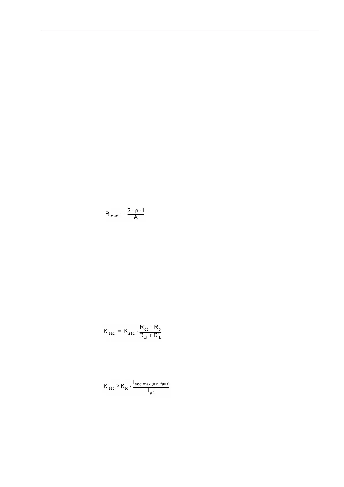
For CT's that are defined by the rated symmetrical short-circuit current factor K
ssc
and
the rated burden R
b
(e.g. 5P, 10P), the effective K’
ssc
can be calculated by the formula:
The minimum required K’
ssc
can be calculated by the formula:
Condition: K’
ssc
(required) ≤ K'
ssc
(r.m.s.)
K
ssc
= rated symmetrical short-circuit current factor
(example: CT 5P20 → K
SSC
= 20)
K'
ssc
= effective symmetrical short-circuit current factor
K
td
= rated transient dimensioning factor
I
scc max (ext.
fault)
= maximum symmetrical through flowing fault current
I
pn
= CT rated primary current
I
sn
= CT rated secondary current
R
ct
= secondary winding d.c. resistance at 75
o
C
(or other specified temperature)
R
b
= rated resistive burden
R'
b
= R
lead
+ R
relay
= connected resistive burden
T
p
= primary time constant (net time constant)
V
k
= knee-point voltage in V (r.m.s.)
R
relay
= relay burden
with:
I = single conductor length from CT to relay in m
ρ = specified resistance = 0.0175 Ω mm
2
/m (copper wires) at 20
o
C
(or other specified temperature)
A conductor cross-section in mm
2
 Loading...


