2 Functions
52
7UT613/63x Manual
C53000-G1176-C160-2
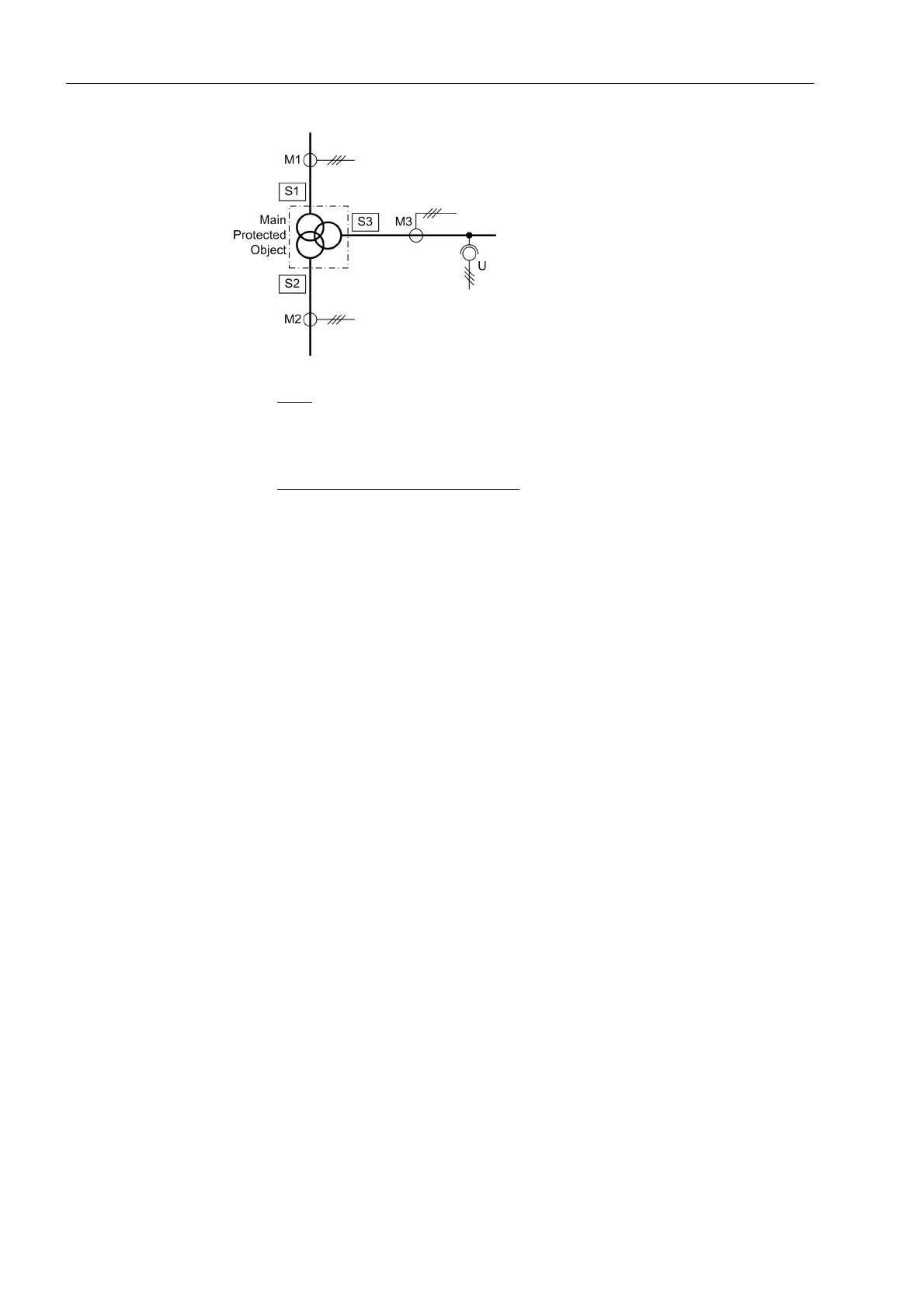
Figure 2-4 Example of a topology on a three-winding transformer
Sides:
S1 High voltage side of the main protected object (power transformer)
S2 Low voltage side of the main protected object (power transformer)
S3 Tertiary winding side of the main protected object (power transformer)
Measuring locations 3-phase, assigned
:
M1 Measuring location, assigned to the main protected object, side 1
M2 Measuring location, assigned to the main protected object, side 2
M3 Measuring location, assigned to the main protected object, side 3
Special Consider-
ations on Auto-
Transformers
As mentioned above, the common windings on auto-transformers must always be
defined as S1 and S2. A third side may be present if the compensation winding is di-
mensioned as power winding (tertiary winding) and accessible (figure 2-5). In this
example we have 3 sides and 4 assigned measuring locations. During parametrization
of the auto-transformer, one must always start with the auto-winding.
 Loading...


