Functions
2.5 Distance Protection
SIPROTEC, 7SD5, Manual
C53000-G1176-C169-5, Release date 02.2011
136
Calculation Example 1:
110 kV-overhead line 150 mm
2
, 3-pole tripping, with the following data:
maximum transmittable power
P
max
= 100 MVA corresponds to
I
max
= 525 A
minimum operating voltage
U
min
= 0.9 U
N
Current Transformer 600 A / 5 A
Voltage Transformer 110 kV / 0.1 kV
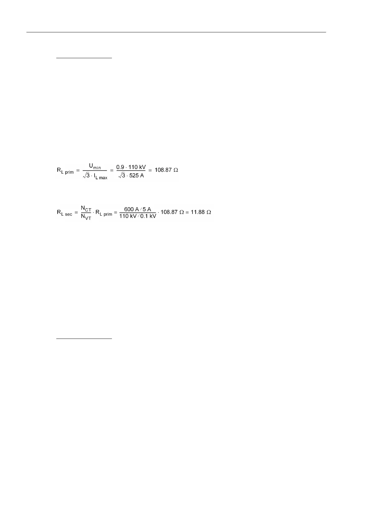
The resultant minimum load impedance is therefore:
This value can be entered as a primary value when parameterizing with a PC and DIGSI. The conversion to
secondary values is
when applying a security margin of 10% the following is set:
R load (Ø-Ø) = 97.98 Ω primary = 10.69 Ω secondary
R load (Ø-E) = 97.98 Ω primary = 10.69 Ω secondary
The spread angle of the load trapezoid characteristic ϕ load (Ø-E) (address 1542) and ϕ load (Ø-Ø)
(address 1544) must be greater (approx. 5°) than the maximum arising load angle (corresponding to the
minimum power factor cosϕ).
Minimum power factor (example)
cos ϕ
min
= 0.63
ϕ
max
= 51°
Setting value ϕ load (Ø-Ø) = ϕ
max
+ 5° = 56°.
Calculation Example 2:
For applications with parallel line (zero sequence mutual coupling) and single pole tripping:
400 kV overhead line (220 km) on double tower with the following data:
Maximum power flow per circuit when both lines in service:
P
max
= 1200 MVA corresponds to
I
max
= 1,732 A
minimum operating voltage
U
min
= 0,9 U
N
Current Transformer 2000 A/5 A
Voltage Transformer 400 kV/0.1 kV
Setting parameter RE/RL 1.54
 Loading...


