Functions
2.6 Power Swing Detection (optional)
SIPROTEC, 7SD5, Manual
C53000-G1176-C169-5, Release date 02.2011
182
2.6.2 Method of Operation
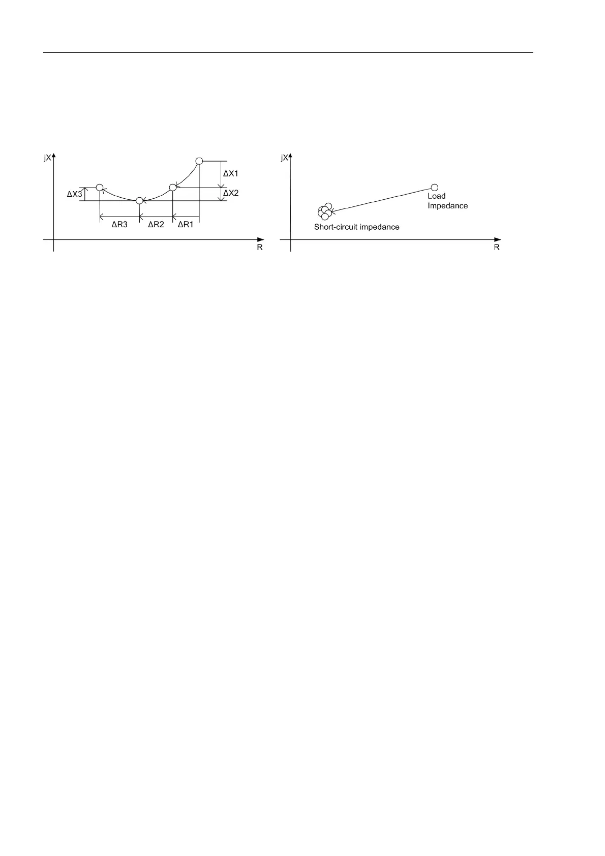
To detect a power swing, the rate of change of the impedance vectors is measured.
Figure 2-77 Impedance vectors during a power swing and during a fault
To ensure stable and secure operation of the power swing detection without the risk of an overfunction of the
power swing detection during a fault, the following measuring criteria are used:
• Trajectory monotony:
During a power swing, the measured impedance features a directional course of movement. This course of
movement occurs exactly when not more than one of the two components ΔR and ΔX features a change of
direction within one measuring window. A fault usually causes a change of direction in ΔR as well as in ΔX
within one measuring window.
• Trajectory continuity:
During a power swing, the distance between two subsequent impedance values features a clear change in
ΔR or ΔX. In case of a fault, the impedance vector jumps to the fault impedance without moving afterwards.
• Trajectory uniformity
During a power swing, the ratio between two subsequent changes of ΔR or ΔX will not exceed a threshold.
A fault usually causes an abrupt jump of the impedance vector from the load impedance to the fault imped-
ance.
The indication of a power swing is triggered when the impedance vector enters the power swing measuring
range PPOL (refer to Figure 2-78) and the criteria of power swing detection are met. The fault detection range
APOL for the polygonal characteristic is made up of the largest quantitative values set for R and X of all active
zones. The power swing area has a minimum distance Z
Diff
of 5 Ω (at I
N
= 1 A) or 1 Ω (at I
N
= 5 A) in all direc-
tions from the fault detection zone. Analog features apply for the MHO characteristics. The power swing circle
also has a distance of 5 Ω (at II
N
= 1 A) or 1 Ω (at II
N
= 5 A) from the largest zone circle. The power swing mea-
suring range has no load trapezoid cutout.

 Loading...


