Functions
2.8 Earth Fault Protection in Earthed Systems (optional)
SIPROTEC, 7SD5, Manual
C53000-G1176-C169-5, Release date 02.2011
238
During the selection of the current and time settings, regard must be taken as to whether a stage should be
direction dependent and whether it uses teleprotection. Refer also to the margin headings „Determination of
Direction“ and „Teleprotection with Earth Fault Protection“.
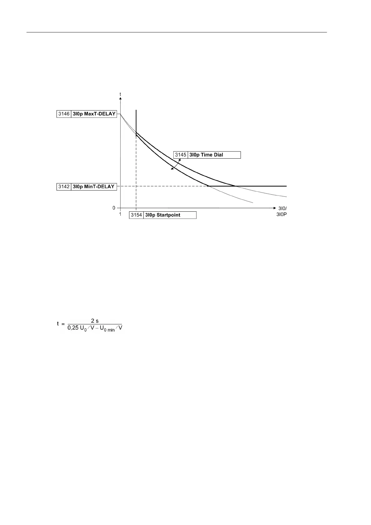
Figure 2-115 Curve parameters in the logarithmic–inverse characteristic
Zero-Sequence Voltage-controlled Stage with Inverse Characteristic
If you have configured the zero-sequence voltage controlled stage (address 131 Earth Fault O/C = U0
inverse), you set the operating mode first: Address 3140 Op. mode 3I0p. This stage can be set to operate
Forward (usually towards line) or Reverse (usually towards busbar) or Non-Directional (in both direc-
tions). If the stage is not required, set its mode to Inactive.
Address 3141 3I0p PICKUP indicates the minimum current value above which this stage is required to oper-
ate. The value must be exceeded by the minimum earth fault current value.
The voltage-controlled characteristic is based on the following formula:
U
0
is the actual zero-sequence voltage. U
0 min
is the setting value U0inv. minimum (address 3183). Please
take into consideration that the formula is based on the zero-sequence voltage U
0
, not on 3U
0
. The function is
illustrated in the Technical Data.
Figure 2-116 shows the most important parameters. U0inv. minimum displaces the voltage-controlled char-
acteristic in direction of 3U
0
. The set value is the asymptote for this characteristic (t → ∞). In Figure 2-116, a'
shows an asymptote that belongs to the characteristic a.
The minimum voltage 3U0>(U0 inv) (address 3182) is the lower voltage threshold. It corresponds to the line
c in Figure 2-116. In characteristic b (asymptote not drawn) the curve is cut by the minimum voltage 3U0>(U0
inv) (line c).
In address 3184, an additional time T forw. (U0inv) that is added to the voltage-controlled characteristic
can be set for directional-controlled tripping.
With the non-directional time T rev. (U0inv) (address 3185) a non-directional back-up stage can be gen-
erated.
 Loading...


