Functions
2.22 Circuit Breaker Failure Protection
SIPROTEC, 7SD5, Manual
C53000-G1176-C169-5, Release date 02.2011
399
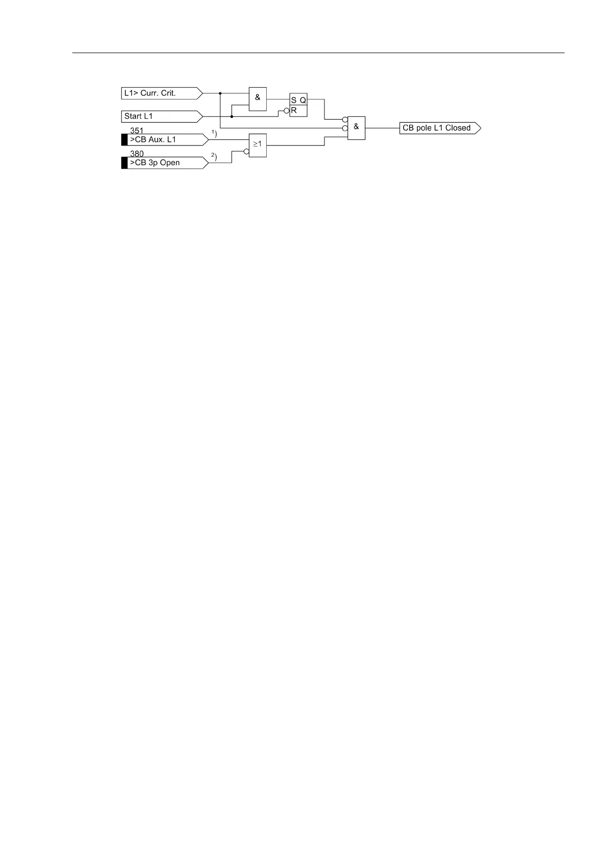
Figure 2-186 Interlock of the auxiliary contact criterion - example for phase L1
1
) if phase-segregated auxiliary contacts are available
2
) if series-connected NC contacts are available
On the other hand, current flow is not a reliable criterion for proper operation of the circuit breaker for faults
which do not cause detectable current flow (e.g. Buchholz protection). Information regarding the position of the
circuit breaker auxiliary contacts is required in these cases to check the correct response of the circuit breaker.
For this purpose, the binary input „>BF Start w/o I“ No. 1439 is provided (Figure 2-188 left). This input
initiates the circuit breaker failure protection even if no current flow is detected.
Common phase initiation
Common phase initiation is used, for example, in systems with only 3-pole tripping, for transformer feeders, or
if the busbar protection trips. It is the only available initiation mode when using the 7SD5 version capable of 3-
pole tripping only.
If the circuit breaker failure protection is intended to be initiated by further external protection devices, it is rec-
ommended, for security reasons, to connect two binary inputs to the device. Besides the trip command of the
external protection to the binary input „>BF Start 3pole“ no. 1415 it is recommended to connect also the
general device pickup to binary input „>BF release“ no. 1432. For Buchholz protection it is recommended
that both inputs are connected to the device by two separate wire pairs.
Nevertheless, it is possible to initiate the circuit breaker failure protection in single-channel mode should a sep-
arate release criterion not be available. The binary input „>BF release“ (No. 1432) must then not be as-
signed to any physical input of the device during configuration.
Figure 2-188 shows the operating principle. When the trip signal appears from any internal or external feeder
protection and at least one current flow criterion according to Figure 2-185 is present, the circuit breaker failure
protection is initiated and the corresponding delay time(s) is (are) started.
If the current criterion is not fulfilled for any of the phases, the position of the circuit breaker auxiliary contact
can be queried as shown in Figure 2-187. If the circuit breaker poles have individual auxiliary contacts, the
series connection of the three normally closed (NC) auxiliary contacts is used. After a 3-pole trip command the
circuit breaker has only operated correctly if no current is flowing via any phase or alternatively all three auxil-
iary contacts indicate the CB is open.
Figure 2-187 illustrates how the internal signal „CB pole ≥L1 closed“ is created (see Figure 2-188 left) if at least
one circuit breaker pole is closed.
 Loading...


