Functions
2.1 General
SIPROTEC, 7SD5, Manual
C53000-G1176-C169-5, Release date 02.2011
47
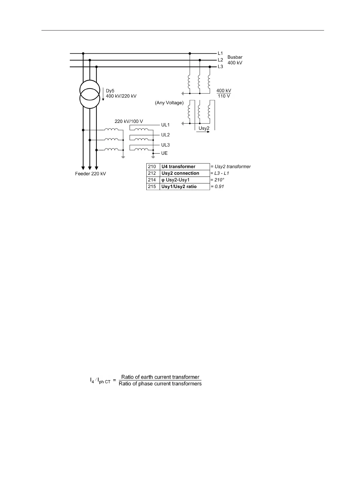
Figure 2-3 Busbar voltage measured via transformer
• Connection of the U
4
input to any other voltage U
X
, which can be processed by the overvoltage protection
function:
Address 210 is then set to: U4 transformer = Ux transformer.
• If the input U
4
is not required, set:
Address 210 U4 transformer = Not connected.
Factor Uph / Udelta (address 211, see above) is also of importance in this case, as it is used for scaling
the measured data and fault recording data.
Current Connection
The device features four current measurement inputs, three of which are connected to the set of current trans-
formers. Various possibilities exist for the fourth current input I
4
:
• Connection of the I
4
input to the earth current in the starpoint of the set of current transformers on the pro-
tected feeder (normal connection):
Address 220 is then set to: I4 transformer = In prot. line and address 221 I4/Iph CT = 1.
• Connection of the I
4
input to a separate earth current transformer on the protected feeder (e.g. a summation
CT or core balance CT):
Address 220 is then set to: I4 transformer = In prot. line and address 221 I4/Iph CT is set:
This is independent of whether the device has a normal measuring current input for I
4
or a sensitive mea-
suring current input (if necessary with I
E
transformer for earth fault protection).
All current transformers in the device must be set to the same secondary current (Jumpers).
 Loading...


