Mounting and Commissioning
3.3 Commissioning
SIPROTEC, 7SD5, Manual
C53000-G1176-C169-5, Release date 02.2011
552
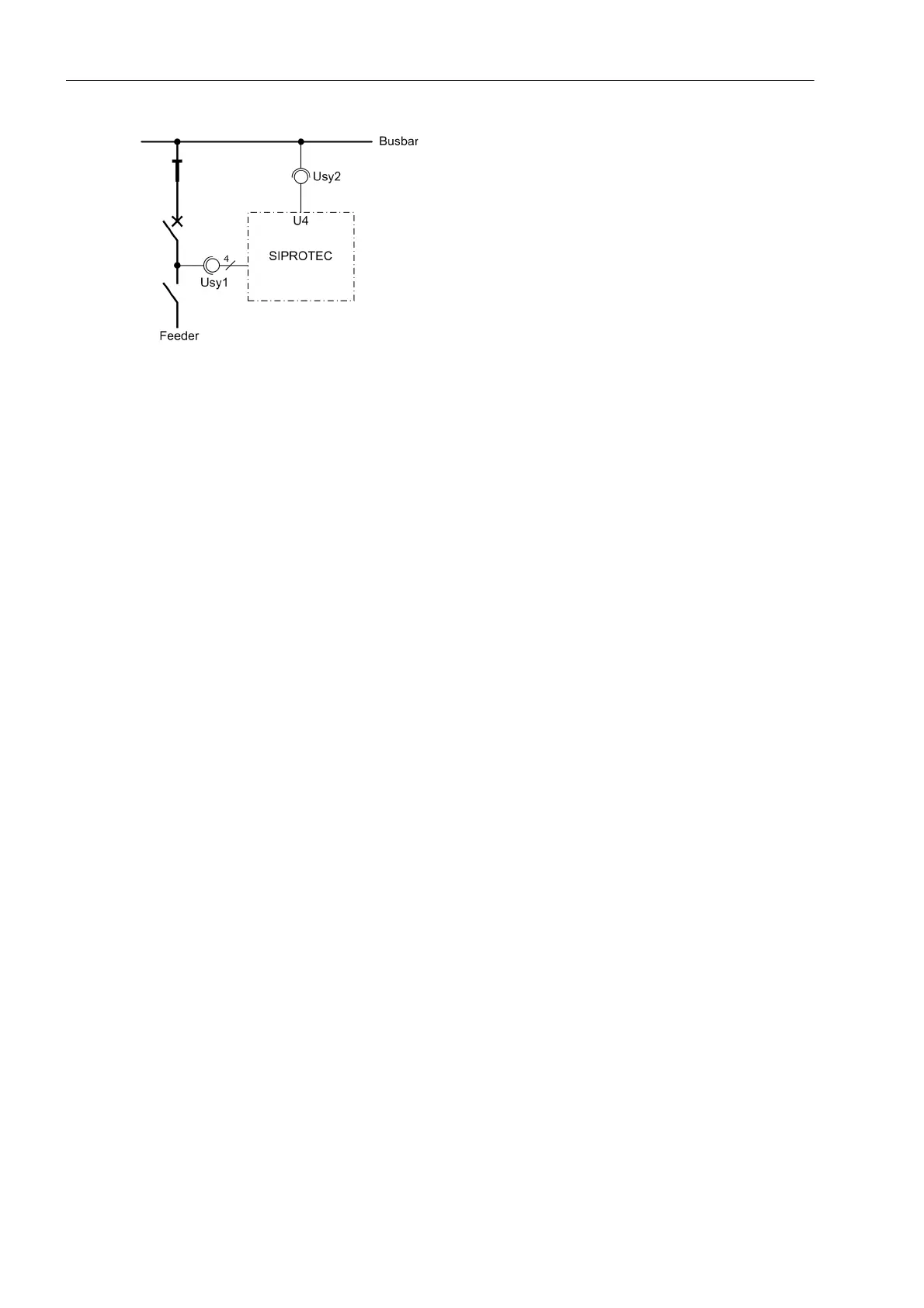
Figure 3-32 Measuring voltages for the synchrocheck — example
• If not, first check whether one of the before named messages 2947 „Sync. Udiff>“ or 2949 „Sync. ϕ-
diff>“ is available in the spontaneous messages.
The indication „Sync. Udiff>“ indicates that the magnitude (ratio) adaptation is incorrect. Check address
215 Usy1/Usy2 ratio and recalculate the adaptation factor, if necessary.
The indication „Sync. ϕ-diff>“ indicates that the phase relation, in this example of the busbar voltage,
does not match the setting at address 212 Usy2 connection (see Section 2.1.2.1). When measuring
across a transformer, address 214 ϕ Usy2-Usy1 must also be checked; this must adapt the vector group
(see Section 2.1.2.1). If these are correct, there is probably a reverse polarity of the voltage transformer ter-
minals for U
sy2
.
• The program AR Usy1>Usy2< = YES (address 3517) and AR SYNC-CHECK = (address 3515) is set for
synchronism check.
• Open the VT mcb of the measuring point U
sy2
(No. 362 „>FAIL:U4 VT“).
• Via binary input (no. 2906 „>Sync. Start AR“) a measuring request is entered. There is no close release.
If there is, the VT mcb for the measuring point U
sy2
is not allocated. Check whether this is the required state,
alternatively check the binary input „>FAIL:U4 VT“ (no. 362).
• Reclose the VT mcb of the measuring point U
sy2
.
• Open the circuit breaker.
• The program AR Usy1<Usy2> = YES (address 3516) and AR Usy1>Usy2< = NO (address 3517) is set for
synchronism check.
• Via binary input (No. 2906„>Sync. Start AR“) initiate the measuring request. The synchronism check
must release closing (message „Sync. release“, No. 2951). If not, check all voltage connections and
the corresponding parameters again carefully as described in Section 2.1.2.1.
• Open the VT mcb of the measuring point U
sy1
(No. 361 „>FAIL:Feeder VT“).
• Via binary input (No. 2906 „>Sync. Start AR“) initiate the measuring request. No close release is given.
• Reclose the VT mcb of the measuring point U
sy1
.
Addresses 3515 to 3519 must be restored as they were changed for the test. If the allocation of the LEDs or
signal relays was changed for the test, this must also be restored.
 Loading...


