Technical Data
4.6 Distance Protection (optional)
SIPROTEC, 7SD5, Manual
C53000-G1176-C169-5, Release date 02.2011
594
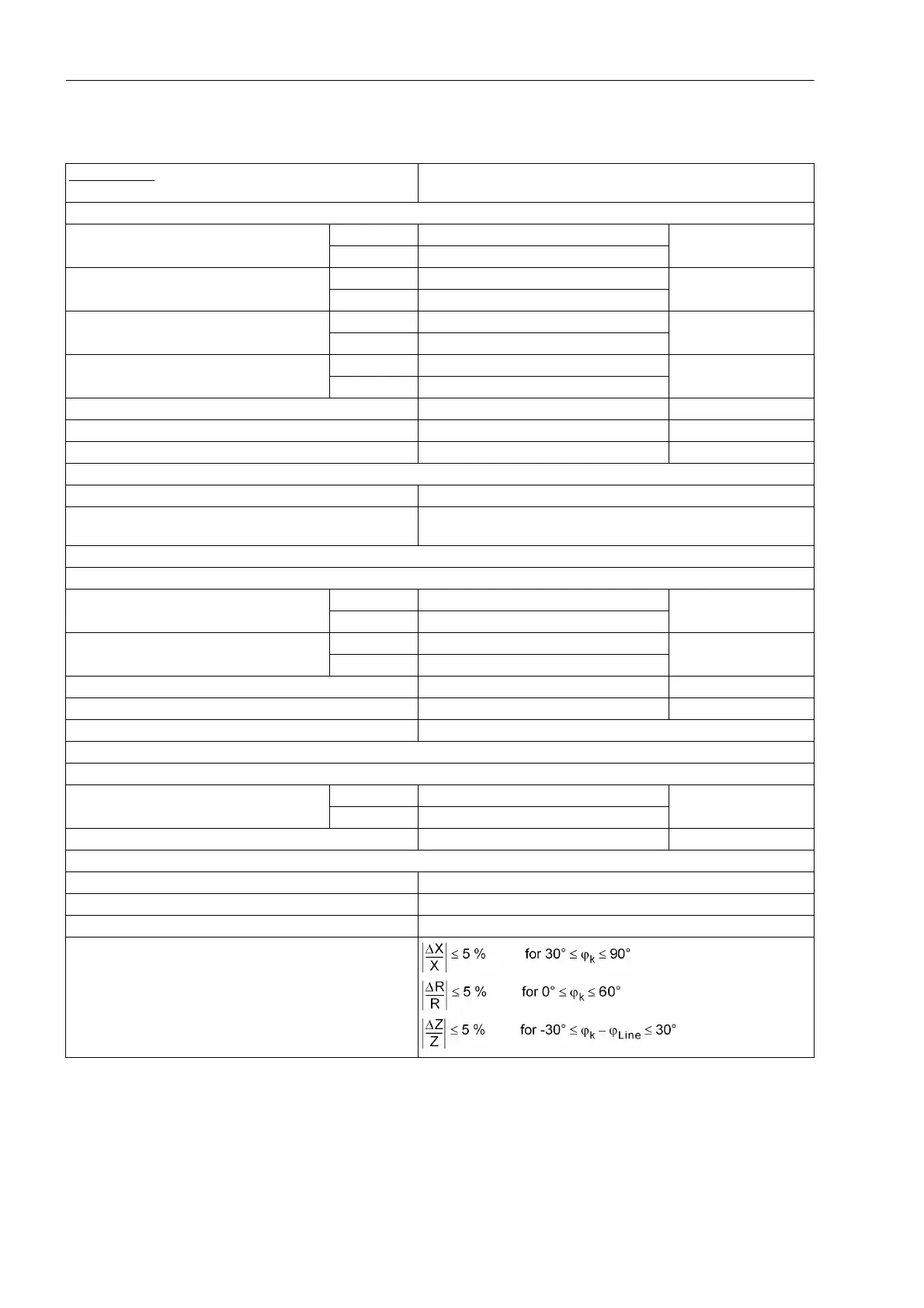
Distance measurement
Characteristic
Polygonal or MHO characteristic (depending on ordered vari-
ant); 6 independent zones and 1 controlled zone
Setting ranges of polygon:
I
Ph
> = min. current phases for I
N
= 1 A 0.05 A to 4.00 A Increments 0.01 A
for I
N
= 5 A 0.25 A to 20.00 A
X = reactance reach for I
N
= 1 A 0.050 Ω to 600,000 Ω Increments 0.001 Ω
for I
N
= 5 A 0.010 Ω to 120,000 Ω
R = resistance tolerance phase-phase for I
N
= 1 A 0.050 Ω to 600,000 Ω Increments 0.001 Ω
for I
N
= 5 A 0.010 Ω to 120,000 Ω
RE = resistance tolerance phase-earth for I
N
= 1 A 0.050 Ω to 600,000 Ω Increments 0.001 Ω
for I
N
= 5 A 0.010 Ω to 120,000 Ω
ϕ
Line
= line angle 10° to 89° Increments 1°
ϕ
Dist
= angle of distance protection characteristic 30° to 90° Increments 1°
α
Pol
= tilt angle for 1st zone 0° to 30° Increments 1°
Direction determination for polygonal characteristic:
For all types of faults With phase-true, memorized or cross-polarized voltages
Directional sensitivity Dynamically unlimited
Stationary approx. 1V
Each zone can be set to operate in forward or reverse direction, non-directional or ineffective.
Setting ranges of the MHO characteristic:
I
PH
> = min. current, phases for I
N
= 1 A 0.05 A to 4.00 A Increments 0.01 A
for I
N
= 5 A 0.25 A to 20.00 A
Z
r
= impedance reach for I
N
= 1 A 0.050 Ω to 200,000 Ω Increments 0.001 Ω
for I
N
= 5 A 0.010 Ω to 40,000 Ω
ϕ
Line
= line angle 10° to 89° Increments 1°
ϕ
Dist
= angle of distance protection characteristic 30° to 90° Increments 1°
Polarization With memorized or cross-polarized voltages
Each zone can be set to operate in forward or reverse direction or ineffective.
Load trapezoid:
R
Load
= minimum load resistance for I
N
= 1 A 0.050 Ω to 600,000 Ω; ∞ Increments 0.001 Ω
for I
N
= 5 A 0.010 Ω to 120,000 Ω; ∞
ϕ
Load
= maximum load angle 20° to 60° Increments 1°
Dropout ratio
– Currents Approx. 0.95
– Impedances Approx. 1.06
Measured value correction Mutual impedance matching for parallel lines (order option)
Measuring tolerances for sinusoidal measured values
 Loading...


