Technical Instructions
Document No. 155-517P25
Rev. 1, July, 2000
Page 16 Siemens Building Technologies, Inc.
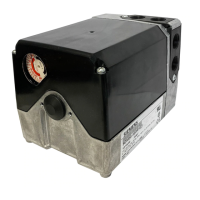
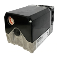
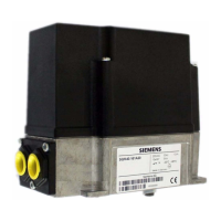
Features of
SQM5x.xxxxxAx
Actuators
Input Signals
The AGA56.1A97… circuit boards accept the following additional input signal:
Line voltage
• Power to A drives the actuator open to the setting of switch cam I (Maximum).
• Power to Z drives the actuator closed to the setting of switch cam II (Economy).
• Power to switch III, terminal 3 drives the actuator to the setting of switch cam III
(Minimum).
Output Signals
The AGA56.1A97 circuit board provides no output signals. Install a double potentiometer
ASZ22…to obtain a 0-1000 Ω actuator position output signal.
Service Guide
WARNING:
Disconnect the power supply to the actuator before performing any service
functions.
NOTE: Most SQM5… actuators are factory configured for counterclockwise (ccw),
minimum to maximum rotation when facing the gear end of the actuator or
clockwise (cw) rotation when facing the other end of the actuator.
Reversing Rotational
Direction
1. Disconnect the double blue wires marked 21 and the double black wires marked 12
from switch I, terminal 21 and switch II, terminal 12 respectively.
2. Connect the double blue wires marked 21 to switch II, terminal 12. Connect the
double black wires marked 12 to switch I, terminal 21.
3. See
Figure 6
. Adjust all switch cams to the desired settings using the red cam drum
scales in combination with the double switch cam pointers.
NOTE: Press and hold the black cam drum release button to rotate the cam drum.
This will give easy access to the switch cams and a better view of the cam
drum scales.
4. If no potentiometer ASZ… is installed, the reversing procedure is complete. If a
potentiometer ASZ… is installed, complete Steps 5 through 11.
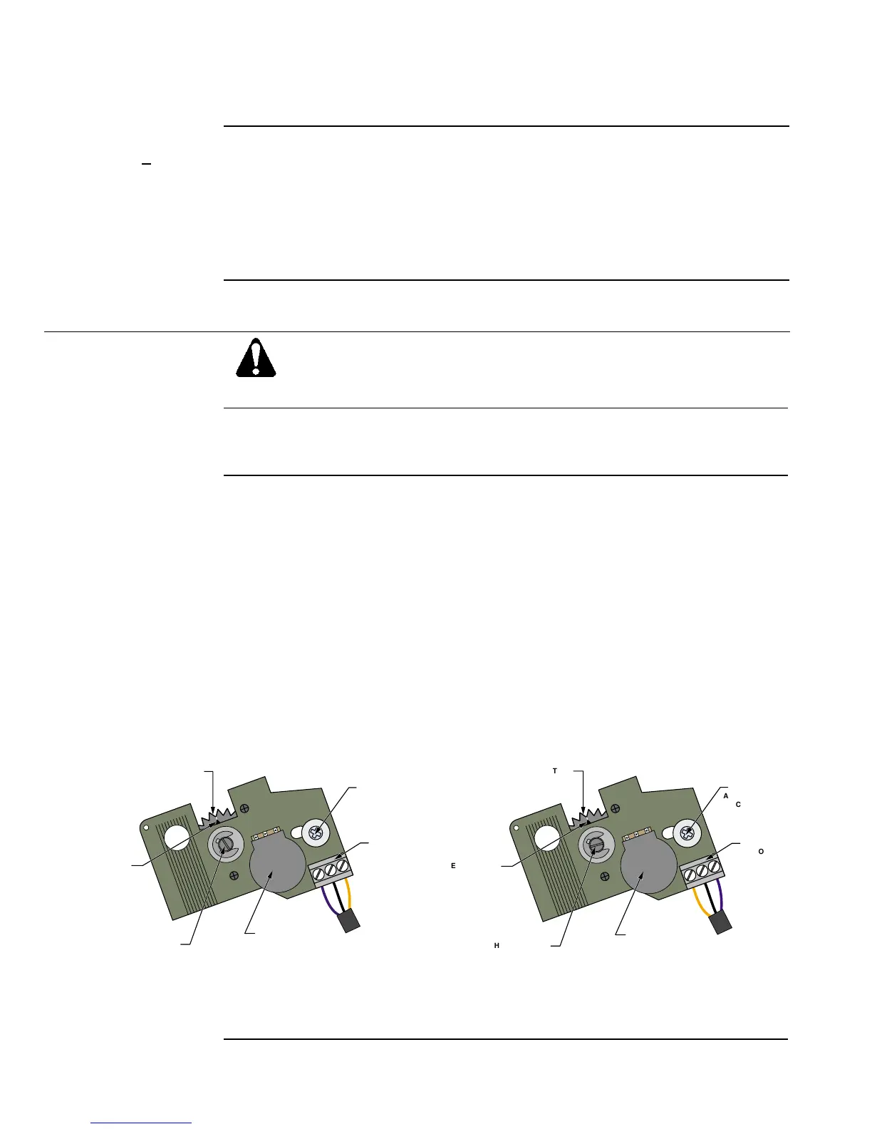
1
BROWN
BOARD
ALIGNMENT
SCREW
TERMINAL
BLOCK
BLACK
BLUE
GEAR WITH MARK "1" FOR
COUNTERCLOCKWISE ROTATION
POTENTIOMETER
POTENTIOMETER GEAR
ATTACHMENT SCREW
POTENTIOMETER GEAR
ALIGNMENT POINTER
EA0517R1
0
BROWN
BOARD
ALIGNMENT
SCREW
TERMINAL
BLOCK
BLACK
BLUE
GEAR WITH MARK "0"
FOR CLOCKWISE
ROTATION
POTENTIOMETER
POTENTIOMETER GEAR
ATTACHMENT SCREW
POTENTIOMETER GEAR
ALIGNMENT POINTER
EA0518R1
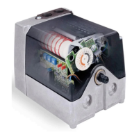
Figure 17. Reversing Rotational Direction on the ASZ Potentiometer Board.
5. See Figure 17. Disconnect the blue and brown wires from the terminal block located
on the ASZ… potentiometer circuit board.
 Loading...