SQM5… Reversing Actuators Technical Instructions
155-517P25
Rev. 1, July, 2000
Siemens Building Technologies, Inc. Page 7
8. Place the second washer onto the “insert end” of the shaft. Using spreading pliers,
install the “C” clip.
Rotational Direction
Verification
Most SQM5… actuators are factory configured for counterclockwise (ccw), minimum to
maximum rotation when facing the gear end of the actuator, or clockwise (cw) rotation
when facing the other end of the actuator. SQM5.xxxxxxxR model numbers, ending with
R are factory configured for clockwise (cw) operation. To field reverse the direction of
rotation, see
Service Guide
, “Reversing Rotational Direction”.
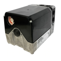
Actuator Mounting
SQM5… actuators can be mounted in any orientation using the four 1/4"-20 UNC tapped
holes located on the bottom corners of the actuator base. Optional base mounting
brackets are available. See Table 2 - Product Numbers for Accessories
. SQM5…
actuators can also be face mounted using self tapping screws in combination with the
various holes on the face of the actuator gear end.
10
0
30
50
0
0
10
0
30
50
0
10
0
30
50
50
10
10
0
30
70
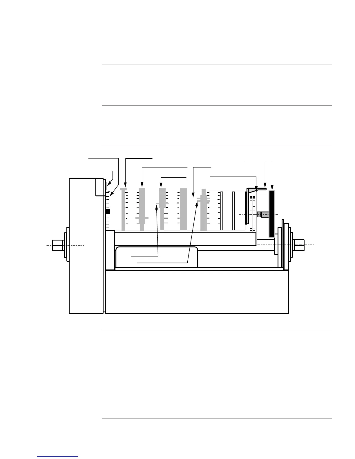
CAM DRUM
RELEASE BUTTON
GEAR END
EA0561R2
ACTUATOR
POSITION SCALE
SWITCH CAM I
SET AT MAXIMUM
SWITCH CAM II
SET AT ZERO ("ECONOMY")
SWITCH CAM III
SET AT MINIMUM
ACTUATOR POSITION
INDICATING POINTER
CAM DRUM
ASZ... (1000 Ohm)
FEEDBACK POTENTIOMETER
BOARD
DIAL POINTER
ACTUATOR POSITION
INDICATING DIAL
SINGLE SWITCH
CAM POINTER
DOUBLE SWITCH CAM POINTER
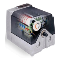
Figure 6. Component Identification on the Cam Drum Side of the SQM5… Actuator.
Switch Adjustment
See
Figure 6
.
All SQM5…actuators are factory wired with Switch I (maximum), Switch II (full closed
“economy position”) and Switch III (minimum). The individual switch cams I, II, and III
are factory set to 90°, 0° and 30° respectively.
NOTE: The single switch cam pointers are used together with the black scales when
configured for counterclockwise (ccw) operation.
The double switch cam pointers are used together with the red scales when
configured for clockwise (cw) operation.
The individual switch cams can be adjusted by hand or with the use of the tool
attached to the outside of the hinged switch terminal protection lid.
 Loading...