SQM5… Reversing Actuators Technical Instructions
155-517P25
Rev. 1, July, 2000
Siemens Building Technologies, Inc. Page 9
Wiring, continued
ALZ
N
AGA56.1A97
SW1
MAN
AUTO
SW 2
12
1213
11 21
M
III
III
IV
V
II
III
I
IV...VIII
"economy"
minimum
maximum
auxilliary
12 22 13 23 14 1524 25
ASZ...
3
4
5
EA0555R2
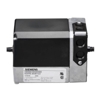
Figure 7. Basic Functional Diagram of AGA56.1…
0
AZ L
AUTO.
MAN.
AGA56.1A97
EA0554R2
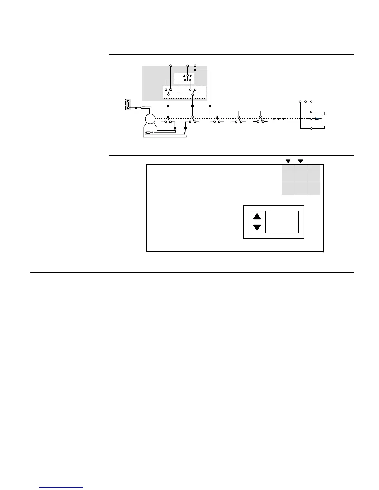
Figure 8. AGA56.1A97 Terminal/Auto-Manual Board.
AGA56.41/42/43…
circuit boards.
See
Figures 9 and 10
.
1. Connect line voltage to terminal L. Terminal L must be powered at all times.
2. Connect neutral to terminal N.
3. Connect ground to the terminal located to the right of the auto/manual switch.
4. For applications where terminals Z, ZL, A and 13 are not used, bridge terminal LR
and L. If any terminals Z, ZL, A or 13 are used, terminal LR must not be bridged with
terminal L. In addition, terminal LR must never be powered simultaneously with any
terminals Z, ZL, A or 13. However, terminal LR must be powered once Z, ZL, A and
13 are no longer powered and modulating operation is required (refer to application
guide for typical installation examples).
5. Connect the input control signal wires to the appropriate terminals.
 Loading...