SQM5… Reversing Actuators Technical Instructions
155-517P25
Rev. 1, July, 2000
Siemens Building Technologies, Inc. Page 17
6. Reconnect the brown wire to the left terminal and the blue wire to the right terminal.
The black wire remains connected to the middle terminal.
7. See Figure 6. Remove the white plastic actuator position-indicating dial by gently
pulling while rotating in the clockwise direction.
8. The actuator position indicating pointer, located near the actuator gear end of the
cam drum, must point to the “0” mark on the actuator position scale (scale on the
cam drum nearest to the actuator gear end). Press and hold the black cam drum
release button while manually rotating the cam drum.
9. See
Figure 17
. Loosen the black potentiometer gear attachment screw
approximately one turn. Gently wedge a small screwdriver between the
potentiometer gear and the gray plastic housing. Gently twist the screwdriver until
the potentiometer gear releases from the cam drum shaft.
10. Manually rotate the potentiometer gear in the counterclockwise direction until the
white line next to the “0” mark on the potentiometer gear face is exactly in
alignment with the potentiometer gear alignment pointer. Firmly tighten the black
potentiometer gear attachment screw while manually holding the potentiometer gear
in alignment. Check the alignment again.
11. Re-install the white actuator-indicating dial by gently pressing it onto the
potentiometer gear attachment screw. Align scale position “0” on the actuator
position indicating dial with the dial pointer by rotating the dial in the clockwise
direction to avoid loosening the potentiometer gear attachment screw.
Shaft Installation
See
Installation and Operation Instructions
.
Preparation before
Circuit Board Installation
WARNING:
Disconnect the power supply to the actuator before replacing the
circuit boards.
The black circuit board mounting bracket,
installed on the inside base of the SQM5…
actuator has four vertical, slotted circuit
board supports. Remove the terminal
section and circuit board(s) from the
mounting bracket.
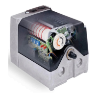
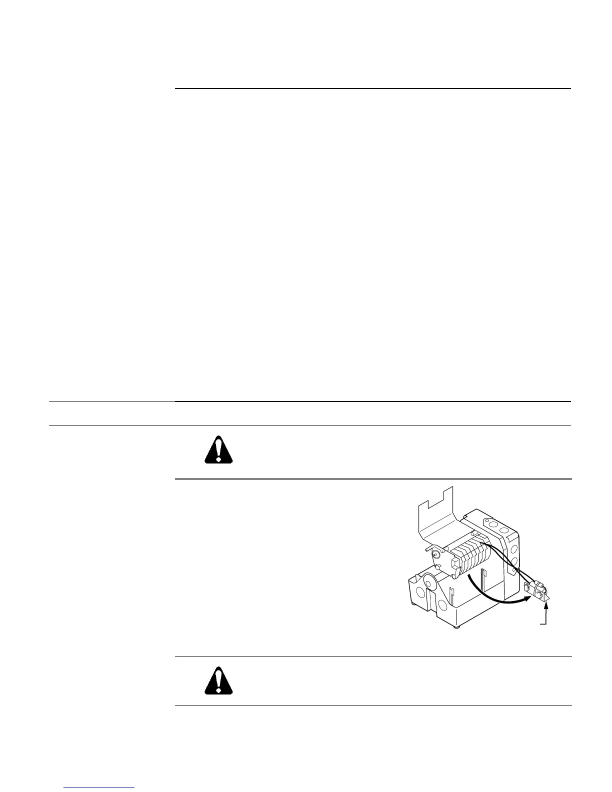
The actuator motor capacitor is attached to
the lower section of the gray plastic switch
housing using snap-on holding clips.
Gently pull the capacitor forward until it
unclips and temporarily place it on top of
the gear housing. See
Figure 18
.
EA0570R1
CAPACITOR
Figure 18.
CAUTION:
Do not disconnect any capacitor wiring.
 Loading...