Technical Instructions
Document No. 155-517P25
Rev. 1, July, 2000
Page 20 Siemens Building Technologies, Inc.
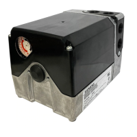
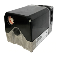
AGA56.9A…
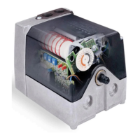
Circuit Board
Installation, continued
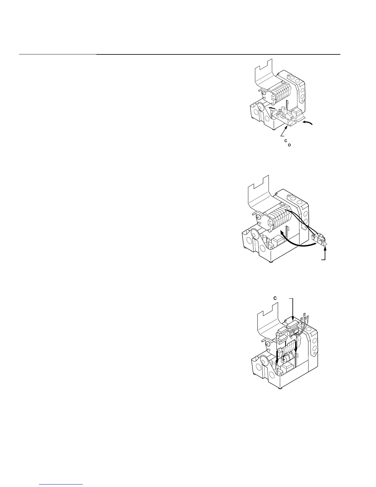
4. Guide the base circuit board from the
switch housing side of the actuator into
the bottom of the circuit board mounting
bracket. See
Figure 23
.
5. Re-install the actuator motor capacitor.
See
Figure 24
.
6. Connect the blue neutral wire, shipped
loose with the AGA56.9A…, to the
spade connector marked N located on
the terminal board just below the
auto/manual switch.
7. Gently guide the terminal board into the
support slots and slide the terminal
board downward until both supports
snap into place. See
Figure 25
.
8. See
Figure 26
and make the following
connections to the actuator:
a. Connect the black wire, marked “1”
from the circuit board to switch I,
terminal 1.
b. Connect the yellow wire, marked “2”
from the circuit board to switch II,
terminal 2. Connect the white wire,
marked “3” from the circuit board to
switch III, terminal 3.
c. Connect the brown wire, marked
“13” from the circuit board to switch
III, terminal 13.
d. Connect the other end of the blue
neutral wire to the double terminal
block located on the outer end of
the switch housing.
e. Connect the gray grounding wire
marked "51" to the ground terminal
located to the right of the
auto/manual switch.
BASE
CIRCUIT
BOARD
EA0571R1
Figure 23.
EA0572R1
CAPACITOR
Figure 24.
EA0573R1
TERMINAL
SECTION
Figure 25
 Loading...