Current
Sensor Wiring Diagrams
Y
v
Circuit
Breaker
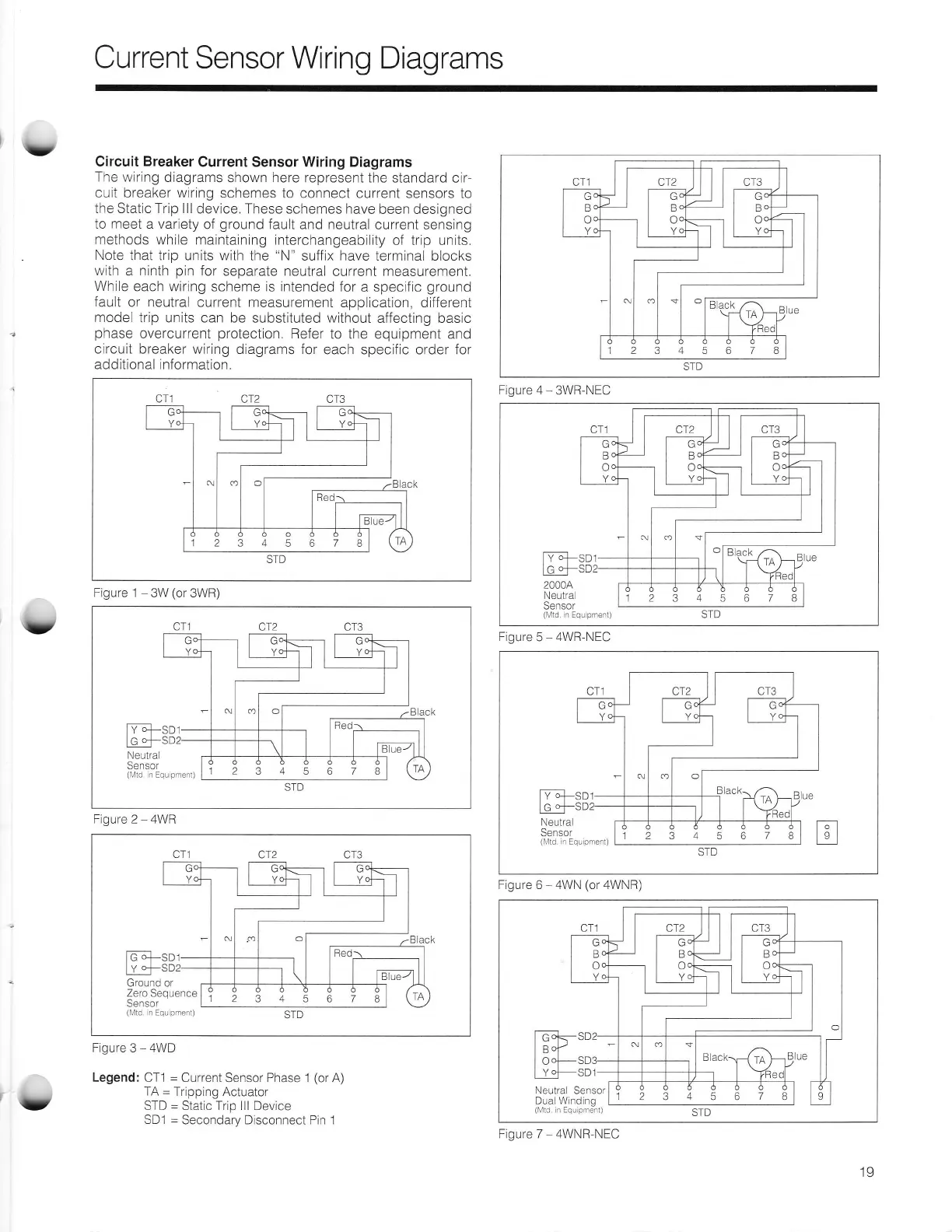
Current Sensor Wiring Diagrams
The wiring
diagrams
shown
here
represent the standard
cir-
cuit breaker wiring
schemes
to connect current sensors to
the Static Trip lll
device, These schemes have
been designed
to
meet
a variety
of
ground
fault and neutral
current sensing
methods
while maintaining
interchangeability
of trip units.
Note
that trip units with
the
"N"
suffix have terminal blocks
with a ninth
pin
for
separate neutral
current
measurement.
While
each wiring
scheme
is intended
for a specific
ground
fault
or neutral current measurement
application, different
model
trip units can be
substituted
without
affecting basic
phase
overcurrent
protection.
Refer
to the equipment and
circuit breaker
wiring diagrams for
each specific order for
additional information.
12345678
Figure 1
3W
(or
3WR)
12345678
Figure
2
-
4WR
[GE-sor
[
-+-soz
Ground or
Zero Sequence
Sensor
(l\4td
in Equ
pmeni)
12345678
Figure
3
-
4WD
Legend:
CTl
=
Current Sensor Phase 1
(or
A)
TA
=
Tripping Actuator
STD
=
Static Trip lll Device
SD1
=
Secondary Disconnect Pin 1
12345674
Figure 4
-
3WR-NEC
12345678
Figure
5
-
4WR-NEC
[vE sor
[q -fsoz
Neutra
Sen
sor
(lVtd
r Equ
pmenl)
12345678
Figure 6 4WN
(or
4WNR)
Ick-sD2
I cd?
lo"l-so:
I
y|-sor
Neutral
Sensor
Dual Wind ng
(lr'l1d
r Equ
pmert)
12345678
Figure 7 4WNR'NEC
,v
19

 Loading...