General
lnformation
Overcurrent Protection
Conf igurations
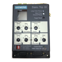
Static
Trip lll
trip
units are available in
six basic overcurrent
protection
configurations
to
meet
specific
protection
require-
ments,
All trip
units have Long Time
fault
protection
with
switchable thermal
memory. This is
designated by the suffix
identifier T immediately
following
the letters RMS in
the catalog
number
designation. AII
trip units include the LCD
target
indicator
and fault
pickup
LED's. The
"-T"
suffix after the basic
overcurrent
protection
identifier
shows
the
LCD
target is
pro-
vided. Zone
interlocking
capability is
also standard on trip
units with
short time or
ground
fault
protection,
but additional
components
and wiring
are
required
to connect
trip units
together into
a
functioning
zone-interlocked
system. fhe
"2"
suffix
indicates
zone interlocking
capability. Available
protec-
tion conf igurations
are:
Protection
Conf iguration
Long Time/lnstantaneous
Long Time/Short
Time
Long Time/Short
Time/lnstantaneous
Long Time/lnstantaneous/Ground
Fault
Long Time/Short Time/Ground
Fault
Long Time/Short
Time/l nstantaneous/
Ground
Fault
LCD Targets
A
custom liquid
crystal display
(LCD) provides
a
visual
indica-
tion of
an overcurrent
tripping action. Target retention is
provided
by capacitive
stored energy in the trip
unit, eliminat-
ing
the need for
batteries. ln addition
to the tripping informa-
tion,
improper
operation
of the
protection
microprocessor
is
displayed
on the LCD. The
displayed legends are:
o
OVERLOAD
-
long
time
delay tripping
.
SHORTCIRCUIT-shorttime
delayor
instantaneoustripping
.
GROUND FAULT
-
ground
fault
delay tripping
o
DISABLED
-
watchdog
circuit indicates
protection
micro-
processor
not f
unctioning
properly
Communications
and Metering Functions
Static
Trip lllC
trip
units
meter
and communicate
phase
cur-
rents;
Static
Trip
IIICP trip
units
meter
and communicate
currents, voltages,
power,
and energy
information.
Neutral
and
ground
current metering
is available
on both models.
(See
table
for
list of
parameters
measured.)
A second microprocessor,
referred
to as the communications
microprocessor,
is
used in these trip
units to
implement
the
communications and metering
functions, A
green
"Comm
Watch' LED, visible from
the front
of the trip unit,
provides
a
visual indication
of the operation
of the second microproces-
sor.
When
the control
powei
is
present
and
the
microprocessor
is
passing
the built-in-test routine,
the LED blinks with
a
half-
second
pulse
every three seocnds. A
burst of
pulses
also
occurs
whenever
the
trip unit is communicating
to a master
device via the RS-485
port
at the back of the unit.
The same
current sensors, used in the overcurrent
protec-
tion function,
are used
in
the current metering
function.
Special
purpose
Potential Transformer
(PT)
modules are
used
in measuring
the voltages,
(see
Accessories section).
The
accuracy of the
integrated
digital metering
functions
is comparable to separate
traditional analog
instrumentation.
O
lncluded
when
ground
fault
protection
specified
@ Requ
res
"N"
option and neutral current sensor
O Only displayed for four wire systems
Two
communications
ports
are available from which to read
the metered data. A
port
on the
front
of the trip unit
provides
access for local monitoring with the
Siemens
BDU Breaker
Display
Unit,
(see
Breaker
Display Un t section). A
port
on the
back of the
trip unit allows the trip unit to be
integrated into
the Siemens ACCESSTT/
electrical distribution communica-
tion system. The metered data can be displayed at a Power
MonitorrNa
panel
or
personal
computer. Network communica-
tions
are over a shielded twisted
pair
data bus, SEAbus.
The
real-time
clock in the trip unit is
periodically
synchronized with
a
master
clock in the network for accurate, to the second, time
stamping of events.
Extended Protective Relaying
Static
Trip ll|CPX
trip units
provide
the same overcurrent
protection,
communications, and metering as the Static
Trip
lllCP model
plus
seven additional
protective
relaying func-
tions.
The
protection
functions have independent
pickup
thresholds
and delays.
The
pickup
and delay set-points
may
be accessed and set remotely via
the communications
bus
or locally via the BDU Breaker Display
Unit,
(see
Breaker
Dlsplay
Unit section), Adjusting of the set-points is
protected
by a
password
to
preventtheir
being changed by unauthorized
personnel.
Viewing
of the set-point
values is
unprotected.
Identifier
RMS-TI-T
RMS-TS.TZ
RMS-TSI-TZ
RN/S-TIG-TZ
RN/S-TSG-TZ
RMS-TSIG-TZ
v
Metering Functions
Measured
Parameiers
l\ilodel
iltc
iltcP
Phase
Current
Avg. Phase
Currents
Ground Current O
Neutral
Current O
oni on1
Phase
Voltages O
Avg. Phase Voltage O
Line Voitages
Avg. Line Vo tage
kW Demand
kW Hours
kW Hours Reverse
KVAR
kVAR Hours
Power Factor
Freq
uency
v
 Loading...
