Metering
and
Extended
Protective
Relaying
The Output
1
contact
located on
the back of
the trip unit
is
used for the Comm Open
function.
The contact
can be con-
trolled by either
the Comm Open
command
or by an
alarm
action,
but not by both.
When Comm Open
is set
to On, the
alarm
functions are
prohibited
from controlling the
contact.
Note that
when
the Comm
Open
is set to On
and an open
command
is
sent
from a
master device, the Output
I contact
will activate and then automatically
deactivate
when the 52b
breaker
position
input indicates
that the circuit
breaker
has
actually opened.
When the Comm Open
is Off,
control of
the
alarm relay output
reverts to the
alarm
function, and
will not
automatically deactivate
when
the circuit breaker
opens.
Default Values
The default values
for the fundamental
configuration
param-
eters are
given
in
the
following table
along
with the source
for
programming proper
values*.
.
Trip unlts shipped separate
y
from the
factory for replacement,
spare or
retrofit
use are al
preprogrammed
to
the default
values shown.
Trip
units
shipped
nsta
led ln
circuit
breakers for
future compartments, spares
or to OEM'S
wi I be
preprogrammed
to the
vaues
given
on the breaker
90-series
drawings
for
breaker-specif c
information such as
phase
current sensors.
Trip units
shlpped
as
part
of complete equipment
shou d be
preprogrammed
to lnclude applica-
tion-specifrc
information such as
phase
rotation and
volt mode.
This information
is included
in
the communcaton
diagram
whch s suppl
ed as
part
of the
standard customer
drawing
packagewith
Siemenstype
R lowvoltage
switchgear'
Similar
means of
recording
proper
values should be used
when the trip
unit is
installed
in
applications
other than Siemens
type
B
switchgear
(consult
equip-
ment suppl er or create
a comparable
documentation
means as
required).
Source
for
Conf
iguration
Parameters
Notes:
OTrip
un ts factory installed
in Type RL
low voltage
power
circult
breakers
are
preprogrammed
to breaker-spec
f ic information shown on
the circuil breaker's
90-series drawrng.
OTrip units
installed in clrcult breakers
shipped
with Type R
low voltage
switchgear
wil be.preprogrammed
to application-speciflc
information shown
on the
communicat ons diagram
suppl ed
with the equipment.
Consu t equlp-
ment manufacturer
if tr
p
un t s supplled
ln other equlpment
or create similar
o Use baud rate
for
specific
system as
requtred
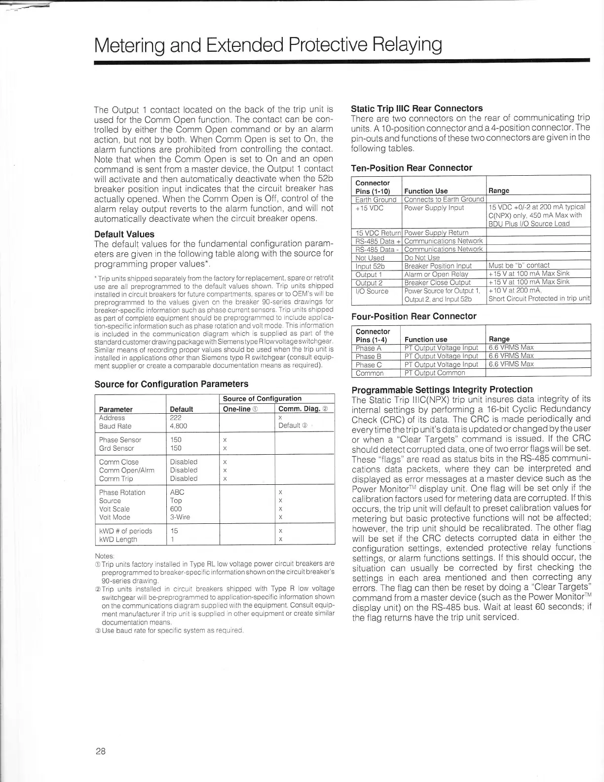
Static
Trip
lllC Rear Connectors
There are two
connectors
on the
rear of
communicating
trip
units.
A
10-position connector
and
a
4-position connector.
The
pin-outs
and functions
of these
two connectors
are
given
in the
following
tables.
Ten-Position
Rear Connector
Programmable
Settings
lntegrity
Protection
The Static
Trip lllC(NPX)trip
unit
insures
data
integrity
of its
internal settings
by
performing
a
16-bit Cyclic
Redundancy
Check
(CRC)
of
its data
The CRC
is made
periodically
and
everytime
the trip
unit's data
is updated
or changed
bythe
user
or
when a
"Clear
Targets"
command
is issued.
lf the
CRC
should
detect
corrupted
data, one
of two
error
f lags will be
set.
These
"flags"
are
read as status
bits
in the
RS-485 communi-
cations
data
packets,
where they
can be
interpreted
and
displayed
as error
messages
at a
master
device
such as
the
Power
MonitorrM display
unit.
One
flag will be
set only
if the
calibration
factors
used
for metering
data are
corrupted,
lf this
occurs,
the trip
unit
will default to
preset
calibration
values
for
metering but
basic
protective
functions
will
not be affected;
however,
the trip unit
should
be recalibrated.
The other
flag
will be
set if the CRC
detects
corrupted
data
in either the
configuration
settings,
extended
protective relay functions
settings,
or
alarm
functions settings.
lf this should
occur,
the
situation
can usually
be
corrected
by
first checking
the
settings
in each
area
mentioned
and then
correcting
any
errors.
The flag can then
be
reset by doing
a
"Clear
Targets"
command
from a
master device
(such
as the
Power
MonitorrM
display
unit) on the
RS-485
bus.
Wait at
least 60 seconds;
if
the
flag returns
have the
trip unit serviced.
Conneclor
Pins
(1-10)
Function Use
Ranoe
Farth
(iround
Connects
to
Earth Ground
+15 VDC Power Supply
Input
'15
VDC
+012 at 200
mA typlcal
C(NPX)
only,
450
rnA Max with
RDI I Plrrs l/O Sorrrce I oad
15 Vt)C Retrrrr Power Suoo v Return
BS-485 Data + Communlcations
Networl.
r1i^nc Nlot\^/^rk
Not I iseri i-)o Nol
L
Jse
Input 52b
Breaker Position lnoul
Must be
"b"
contacl
Output
l
Alarm or open
Helav
15 V at 100
mA Max S
nk
Outout i
Breaker O ose Olrlnul +15 V at 100
mA Max 5
nK
IiU SOUTCE
Power Source
tor Output
1
Output
2, and
lnput 52b
+10
V
at
200 mA.
Short
Circult
Protected
in triP
un
Four-Position
Rear Connector
Connector
Pins
(1-4)
Function use
Ranqe
Phase
A PT Output
Voltaqe
lnput
6.6 VRMS
Max
Phase B PT Ouinul Voltaoe ln0ut
ti ti \/Ht\ls Max
Phase C
PT OutDUt Voltaoe Inout
6.6
VRMS Max
(lommon
PT OutDUt Common
Parameler
Default
Source of Confiouration
One-line O Comm.
Diaq. o
AOOTESS
Baud Rate
222
4,800
X
Default @
Phase Sensor
Grd Sensor
150
150
X
X
Comm C ose
Comm OpeniA
rm
Comm Trip
Dlsabled
D sabled
Disabled
X
X
X
Phase Botat on
Source
Vo t Scale
Volt l\,4ode
ABC
Top
600
3-Wire
X
X
X
x
kWD # of
periods
kWD Length
15
l
X
x
28

 Loading...