Testing
High
Potential
and Megger Testing
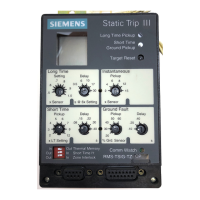
Static Trip lll
trip units
are designed as
part
of an integrated
tripping
system
and are not intended for
direct
connection to
high voltage
sources.
CAUTION: lnjection
ol
high
potential
to any of the trip unit
connections
(including
current sensor inputs,
tripping
actuator
outputs, PT module
voltage inputs,
control
power
input,
RS-485
communications
output
or sub D connec-
tions on
the
front
of
the unit) may
cause damage to the trip
device or
other
portion
of the tripping
system
including
associated
accessories. Therefore
to
properly perform
high
potential
or
megger
testing on electrical
equipment
which
contains circuit
breakers with
Static
Trip llltripping
systems,
the
following
precautions
should be observed:
1. The tripping
system's
current sensors
provide
adequate
high voltage isolation
from
the
primary
circuits
to allow
normal
high
potential
or megger
testing between
phases
or
from
phase
to
ground
without
damage to the
tripping
system.
Do not
apply high voltage
to any of the tripping
systems
secondary connections
such as the
current sensor
output terminals
or the
trip unit connection
terminal block,
2. For
circuit breakers
equipped with
communicating model
trip devices,
do not
apply
high
voltage
to the communica-
tions secondary
disconnect
or to the RS-485
communica-
tions bus and 15V
dc
power
supplywiring in the
equipment
or on
the circuit
breaker itself.
3
Circuit breakers
equipped with
power
metering model
trip
devices
use specially-designed
PT modules
to
pro-
vide isolated
voltage inputs
to the trip
device. These PT
modules
are designed
to
withstand
brief
high
potential
testing at up to 2200Y
ac
without
damage to the trip unit
or
the
PT module
itself . While inadvertent high
potential
or
megger testing
should not cause damage, it will
give
erroneous readings. Therefore
the PT module should be
taken out of the circuit being
tested,
lust
as
is normally
done
for
traditional instrumentation, For cases where the
PT module's input
connections are made to the circuit
breaker
primary
conductors,
simply
rack
the breaker to
the disconnected
position
to
perform
high
potential
or
megger
testing on the electrical equipment bus or cable
runs.
Otherwise,
remove
the PT module
primary
fuses to
test the equipment
or the breaker itself. Refer to circuit
breaker
or equipment wiring diagrams to determine how
the PT module is
used in
your
application.
Communicating model trip devices include low-level out-
puts
which may
be
wired
into alarm or remote open/close
control circuits. When
used, these outputs are wired into
their respective
control circuits through interposing relays
which
should be indicated
on the equipment and/or circuit
breaker wiring
diagrams. The control circuit side of the
interposing relays
can be tested as is normally done for
secondary wiring. Do not
use high
potential
testing on the
trip unit side
of the
interposing relay
circuits.
Trip
units
with
Short Time or
Ground
Fault
protective
functions may
be
wired
together into a zone interlocking
system. Zone interlocking
couplers, expanders or multi-
plexer/translator
devices are
used to
make
these con-
nections
between devices. Do not use high
potential
testing on these zone interlocking
connections.
5.
JJ
 Loading...
