Metering
and
Extended
Protective Relaying
l5r
the RS-485
communications
bus.
This
requires that the master
network
device
(such
as
the
Power
MonitorrM display and
monitoring unit) first
put
relay output
control
in
manual mode
before open or close
commands can be issued. While in
manual
mode, alarm functions
are blocked from
automatically
opening
or closing relay
contacts; although alarm activation
and deactivation
events will still
be
recorded
in the trip unit's
event
log.
Note that manual
operation of the relay
output
contacts
using commands issued
over the RS-485 bus will be
recorded
as
"relay
comm
open" or
"relay
comm close" mes-
sages in the
event log.
Operation of alarm functions is not
directly affected by the
circuit breaker
position.
lf
an alarm
function
is set on and
becomes active or inactive,
associated messages will
be
recorded in
the event log
even with the circuit breaker open.
Likewise, if relay
output control has
been set to on, relay
contacts will
open or close regardless
of circuit breaker
position.
This
operating
characteristic must be kept in mind
when
using the relay
output contacts for control logic, inter-
locking,
annunciation or
other applications and when setting
alarm limits.
Relay output
control cannot be
set to
yes
unless the alarm
mode is
seton. This
effectively
provides
three
possible
operating
modes for
each alarm function
as summarized in the table
below.
O The event log is read
using the RS-485 communlcations
port
and contains
trme-stamped lnformation
about the most recent
alarm actlvation and deac-
tivation events. When
the
relay
output control is set to
yes,
the event
log
also
identifies whlch function
causes the relay
to close and the function which
allows the
relay
to open.
@
Note
that setting the relay
output
for
manual control using the FS-485 com-
munlcations
bus will block control
due to alarm actlvatlon and deactivation.
@
The
alarm log is read us ng
the
BDU
accessory and contalns nformation about
the alarm
function
whlch
causes the
most recent
relay output contact c osure.
Note: lf
a trip unit is moved to a
circuit breaker with different
size sensors, which require
the
phase
sensor and
possibly
the
ground
sensor values
to be
reentered,
check the alarm limits
to insure
that their settings are
compatible
with
the different
sensor values.
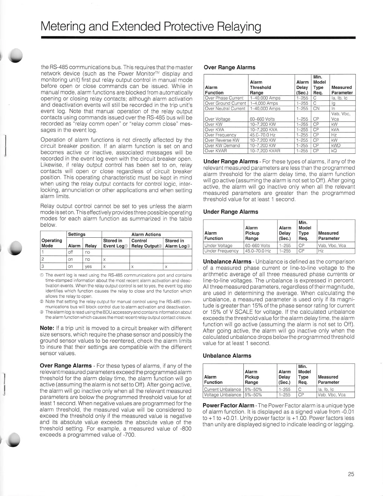
Over
Range Alarms
-
For these
types of alarms, if any of the
relevant
measured
parameters
exceed the
programmed
alarm
threshold for the alarm
delay time, the alarm function will
go
active
(assuming
the alarm is not
set to Off).
After
going
active,
the alarm will
go
inactive
only when all the relevant measured
parameters
are below
the
programmed
threshold value for at
least 1 second. When
negative values
are
programmed
for the
alarm threshold,
the measured value will
be considered to
exceed
the threshold
only
if
the measured value is negative
and its absolute
value exceeds
the absolute value of the
threshold
setting. For example,
a
measured
value of
-800
exceeds a
programmed
value of
-700.
Under
Range Alarms
-
For
these types of alarms,
if any of the
relevant measured
parameters
are
less
than the
programmed
alarm threshold for the alarm delay time, the alarm
function
will
go
active
(assuming
the alarm
is not set to
Off)
After
going
active, the alarm will
go
inactive only when all the
relevant
measured
parameters
are
greater
than the
programmed
threshold
value for
at
least I
second.
Under Range Alarms
Unbalance
Alarms
-
Unbalance
is
defined
as the comparison
of a measured
phase
current or line-to-line voltage to the
arithmetic average of all three measured
phase
currents
or
line-to-line voltages. The
unbalance
is
expressed
in
percent.
Allthree measured
parameters,
regardless
of their
magnitude,
are used in determining
the average.
When calculating the
unbalance, a measured
parameter
is used only if its magni-
tude
is
greater
than 15% of the
phase
sensor
rating for current
or 157o
of
V
SCALE
for voltage. If the calculated unbalance
exceeds the threshold value for the alarm delay time, the alarm
function will
go
active
(assuming
the alarm
is not
set
to
Off).
After
going
active, the alarm
will
go
inactive
only
when the
calculated unbalance
drops below the
programmed
threshold
value for at least 1 second,
Unbalance
Alarms
Power Factor Alarm
-
The Power Factor alarm is a unique type
of alarm
function. lt
is displayed as a signed
value from
-0.0-1
to +1
to
+0.01.
Unity
power
factor is +1.00. Power factors less
than unity are displayed
signed to
indicate leading or lagging.
Over
Range Alarms
Alarm
Function
Alarm
Threshold
Flande
Alarm
Delay
asec I
Min.
Model
Type
Fleo
Measured
Parameter
ver Phase
Current
'1
40,000 Amos
255 la lh Ic
:)ver
(lround
Crrrrent 1-4 000 Amns 1 255 lo
Jver Neutral Current 1 40.000 AmDS 1 255
CN
in
Over
Voltaqe
60 660 Volts
1 255
CP
Vab, Vbc,
Vca
ver KW
10-7,200
KW
1-255 CP
Jver KVA I 0-7.200 KVA 1-255 OP
Over Freouencv 45.4 /Q.Q tz 1 255
-P
lz
Over Reverse KW 10 7 200 KW 1 255
AD
Over
KW Demand 10 7,200 KW 1 255
CP
KWD
Over KVAR
]O 7,200 KVAB
1 255 CP k(l
Operating
Mode
Settinqs
Alarm Actions
Alarm
Relay
Stored
in
Event LoqO
Control
Belav OutDUtO
Stored in
Alarm Loo@
off no
2
on no
x
3 on
yes
x
X
x
Alarm
Function
Alarm
Pickup
Range
Alarm
Delay
(Sec.)
Min.
Model
Type
Req.
Measured
Parameter
Under Voltaoe 60-660 Volts
L_2f,f,
CP Vab, Vbc,
Vca
Under
Frequency
45.0-70.0 Hz
I.ZCJ
CP Lz
Alarm
Function
Alarm
Pickup
Range
AIarm
Delay
(Sec.)
Min.
Model
Type
Req.
Measured
Parameter
Current Unbalance 1-255 C la. b. lc
Voltaoe Unbalance
1,255
CP
Vab, Vbc, Vca
rb/
25

 Loading...