TX-I/O Modules
TX-I/O Module Assembly
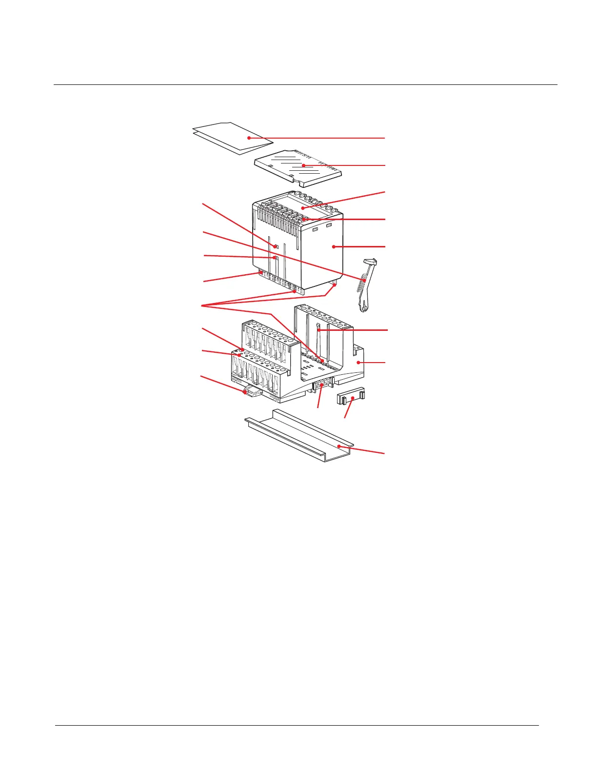
The following figure shows the general TX-I/O Module components and hardware
features.
1
2
3
4
5
6
7
8
9
10
11
12
13
14
15
16
17
18
TXIO0028R1
I/O Module Assembly.
1 Standard DIN mounting rail (not included) 10 Electrical contact between terminal base and
plug-in module
2 Terminal base (plug-in base for the I/O
module)
11 Terminal screws
3 Plug-in module (the functioning component of
the I/O module assembly)
12 Test pickups (test points)
4 Local override facility (not applicable to all
types)
13 Slide fitting to lock assembly into position on
standard mounting rail
5 LCD display (not applicable to all types) 14 TX-I/O bus connector
6 Detachable label holder 15 TX-I/O bus connector cover
7 Module label (not included) 16 Module lock
8 Address key with mechanically encoded
module address
17 Module disengage catch
9 Plug-in contacts between the terminal base
and the plug-in module
18 Module release catch
13
Siemens Industry, Inc. TALON TX-I/O Modules and Island Bus Technical Reference
588-587 CONFIDENTIAL: For internal use only 4/6/2010
 Loading...


