TX-I/O Island Bus
Power Supply Wiring
Bus Connection Module
2
13579111315
(1)
(1)
(2) (3) (4) (5) (6) (7) (8)
4
(2)
6
(3)
5
(4)
10
(5)
12
(6)
14
(7)
16
(8)
2
13579111315
(1)
(1)
(2) (3) (4) (5) (6) (7) (8)
4
(2)
6
(3)
5
(4)
10
(5)
12
(6)
14
(7)
16
(8)
1
2
CS CD
24V
T
CS CD
BCM
24V24V
CS CD
24V
T
CS CD
2
13579111315
(1)
(1)
(2) (3) (4) (5) (6) (7) (8)
4
(2)
6
(3)
5
(4)
10
(5)
12
(6)
14
(7)
16
(8)
2
1357911
(1)
(1)
(2) (3) (4) (5)
4
(2)
6
(3)
5
(4)
10
(5)
PS
PXC0009WDR1
3-WIRE
COMMUNICA
TION
T
O
COMP
ACT
(IF REQUIRED)
2-WIRE
COMMUNICA
TION
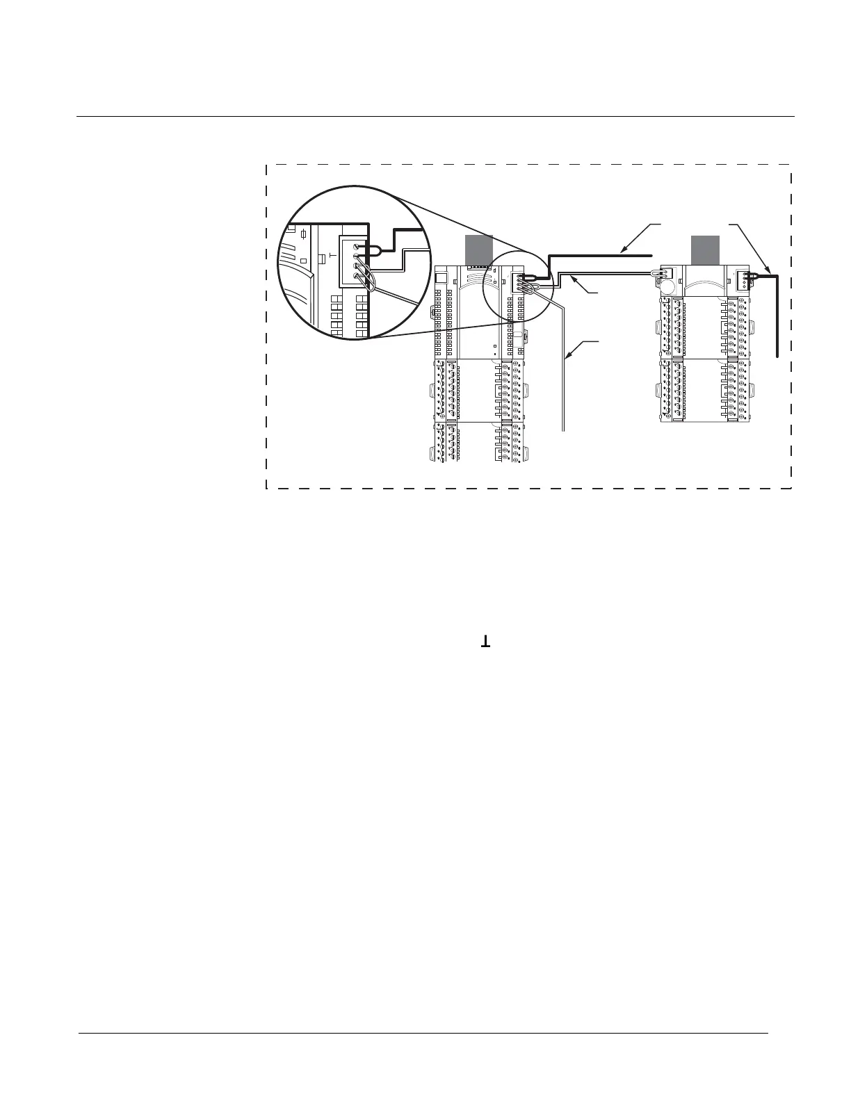
2-WIRE POWER
WIRING DIAGRAM IF ALL COMPONENTS ARE INSIDE THE SAME ENCLOSURE.
24V~ CS CD
24V~
TX-I/O Power Supply to Bus Connection Module Wiring.
TC-36
TX-I/O Modules do not need to be powered off of the same AC source as the TC-36.
The island bus driver circuit in the TC-36 is isolated from the power supply of the TC-
36 itself.
The CD, CS, and System Common (
) signals from the TX-I/O Power Supply module
that is connected to the TX-I/O Modules are brought back and tied to the TC-36 at
terminals 82, 83, and 84.
43
Siemens Industry, Inc. TALON TX-I/O Modules and Island Bus Technical Reference
588-587 CONFIDENTIAL: For internal use only 4/6/2010
 Loading...


