TX-I/O Power Supply and Bus Modules
TX-I/O Power Supply Product Diagram
24V24V
1
2
3
4
5
6
CS CD
24V
T
CS CD
TXIO0046R1
2
3
1
4
6
5
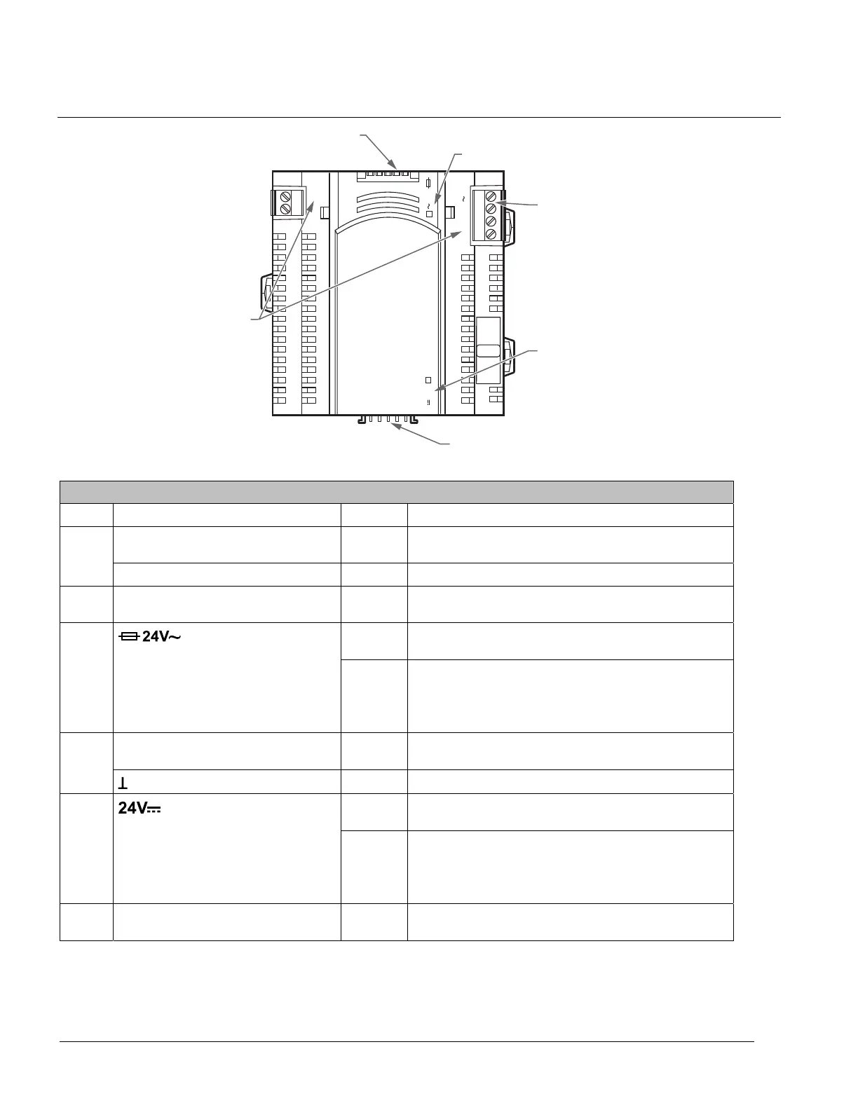
TX-I/O Power Supply Features, Symbols, and Status LEDs.
LED, Symbol, or Feature Status Indication
CS - 24 Vdc Communication Supply for I/O modules and field
devices.
1
CD - Communication Data (Island bus signal).
2 TX-I/O bus connector (female) - Connection for the TC Modular, or left covered if at the
start of a TX-I/O bus. No field device supply.
ON Normal operation. 24 Vac (supply voltage) input present;
fuse is intact.
3
Fuse LED for 24 Vac supply to
peripheral devices
OFF Error.
- No 24 Vac (supply voltage) input.
- Fuse is blown. (4A, 5 × 20 mm, 250V, medium-acting,
ceramic fuse)
24V~ - 24 Vac, supply voltage for the Power Supply module
and field devices.
4
- System neutral.
ON Normal operation. 24 Vdc bus voltage is in the
acceptable range.
5
(green)
LED for 24 Vdc module supply/field
supply voltage (conductor CS,
measured on bus)
OFF Error. 24 Vdc bus voltage is outside the acceptable
range.
- Insufficient or shorted I/O bus supply.
- An AC/DC converter is faulty.
6 TX-I/O bus connector (male) - Connection for TX-I/O Modules. Includes field device
supply.
32
Siemens Industry, Inc. TALON TX-I/O Modules and Island Bus Technical Reference
588-587 CONFIDENTIAL: For internal use only 4/6/2010
 Loading...


