TX-I/O Modules
17
Siemens Industry, Inc. TALON TX-I/O Modules and Island Bus Technical Reference
588-587 CONFIDENTIAL: For internal use only 4/6/2010
TX-I/O Module Symbols and Status LEDs
ON Manual operation; a local override is active.
OFF No voltage or manual operation off.
7 Override status LEDs (yellow)
Flashing or pulsing - Override action
- Remote override
- Output: Local override is off, operation is not possible.
- Input: Operation is not possible.
8 LCD signal display - Only on a TX-I/O modules with –ML suffix.
9 Local override switch - Only on a TX-I/O with –M or –ML suffix.
- Status of the inputs and outputs (peripheral devices). LEDs
are labeled with the I/O point number.
ON Binary value indication.
OFF No voltage or binary value indication.
10 I/O status LEDs (green)
Flashing or pulsing - Fault indication
- Activity of field devices
- Module unconfigured, no address key
- Analog value indication
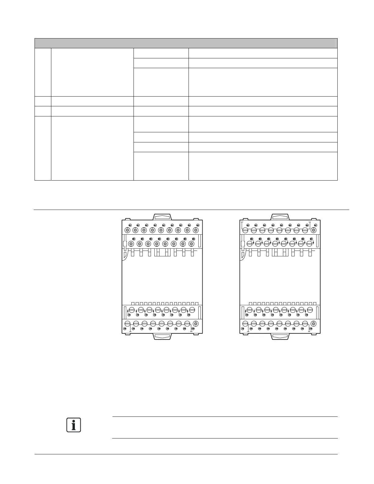
Digital Input Modules (TXM1.8D and TXM1.16D)
TXIO0022R1
TXM1.8D
2
31 5 7 9 11 13 15
(1)
(1)
(2) (3) (4) (5) (6) (7) (8)
4
(2)
6
(3)
8
(4)
10
(5)
12
(6)
14
(7)
16
(8)
TXIO0020R1
TXM1.16D
2
31 5 7 9 11 13 15
(2)
(1)
(4) (6) (8) (10) (12) (14) (16)
(9) (10) (12)(11) (13) (14) (15) (16)
4
(2)
6
(3)
8
(4)
10
(5)
12
(6)
14
(7)
16
18
19 21 23 25 27 29 31 33
20 22 24 26 28 30 32
(8)
The TXM1.8D and TXM1.16D are dedicated to monitoring, respectively, 8 and 16
digital input points.
They monitor status signals from normally open (NO) or normally closed (NC),
latched voltage free/dry contacts.
All 8 points on the TXM1.8D module as well as 8 of the 16 points on the TXM1.16D
module may be used as pulse counters up to 10 Hz.
Each input point has a green LED for status indication.
NOTE:
Potential free (dry contact) for all points.
 Loading...


