24 007-5633-001
3: System I/O Interfaces Overview
RJ-45 (Ethernet) Connectors
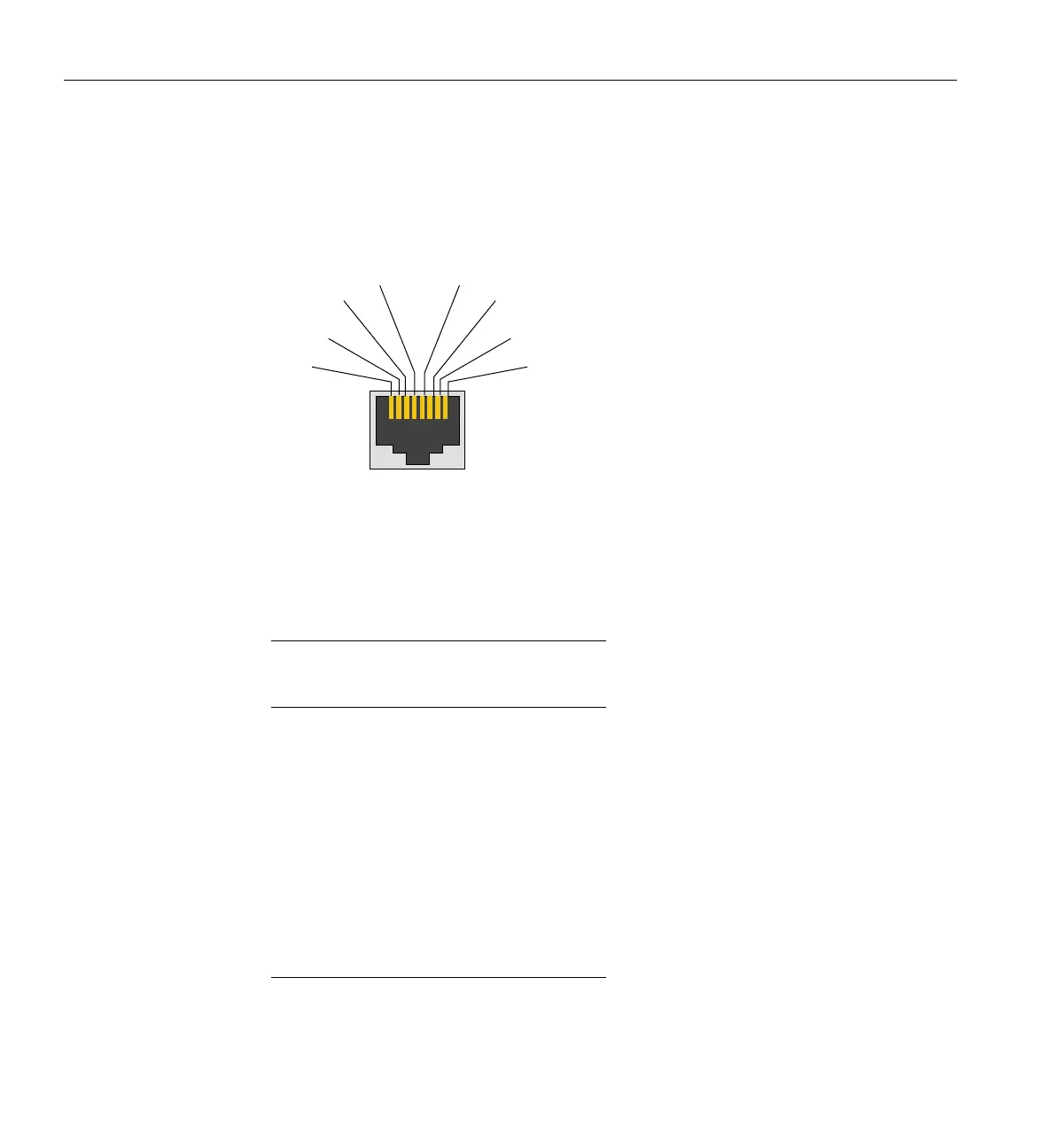
Figure 3-4 shows an example of the RJ-45 connector used on the Octane III with its pin
assignments called out.
Figure 3-4 RJ-45 Ethernet Connector Pin Assignments
Table 3-3 shows the pin assignments for the RJ-45 connector used on the I/O panel of the
Octane III system. The number of functional RJ-45 connectors on the rear of the system is directly
dependant on the use of an optional internal Gigabit Ethernet switch.
Table 3-3 Ethernet Connector Pin Assignments
GigE (1000BaseT)
Ethernet Pinouts
Pin
GigE (1000BaseT) Ethernet
Pinouts
Assignment
1 Transmit/Receive 0+
2 Transmit/Receive 0–
3 Transmit/Receive 1+
4 Transmit/Receive 2+
5 Transmit/Receive 2–
6 Transmit/Receive 1–
7 Transmit/Receive 3+
8 Transmit/Receive 3–
Pin 6
Pin 7
Pin
in 1
Pin 2
Pin 3
Pin 4 Pin 5

 Loading...