EasyManuals Logo

SimCom SIM7000G User Manual

SimCom SIM7000G
63 pages
To Next Page IconTo Next Page
To Previous Page IconTo Previous Page
Page #22 background imageLoading...
Page #22 background image
Smart Machine Smart Decision
SIM7000 _Hardware Design _V1.00 2017-05-23
3 Interface Application
3.1 Power Supply
Pin 55, pin 56 and pin 57 are VBAT power input.
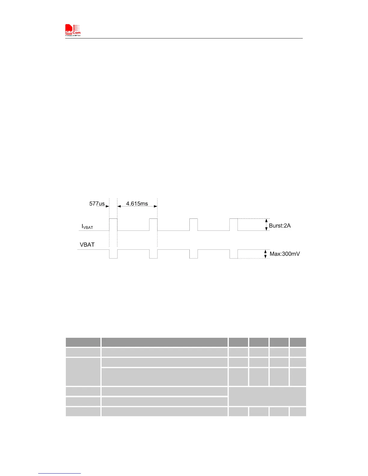
On VBAT pads, the ripple current up to 0.6A typically due to LTE CAT-M1emission burst and up
to 2A typically due to GSM/GPRS emission burst (every 4.615ms). It may cause voltage drop. So
the power supply for these pads must be able to provide sufficient current up to more than 2A in
order to avoid the voltage drop is more than 300mV.
The following figure shows the VBAT voltage ripple wave at the maximum power transmit phase
in GSM emission mode.
Figure 5: VBAT voltage drop during burst emission (GSM/GPRS)
Note: The test condition: The voltage of power supply for VBAT is 3.8V, Cd=100 µF tantalum
capacitor (ESR=0.7Ω) and Cf =100nF (Please refer to Figure 6—Application circuit).
Table 6: VBAT pins electronic characteristic
Symbol
Description
Min.
Typ.
Max.
Unit
VBAT
Module power voltage
3.0
3.8
4.3
V
I
VBAT(peak)
Module power peak current in GSM emission mode.
-
2
-
A
Module power peak current in LTE CAT-M1emission
mode.
-
0.6
-
A
I
VBAT(average)
Module power average current in normal mode
Please refer to the table 32
I
VBAT(sleep)
Power supply current in sleep mode
I
VBAT(power-off)
Module power current in power off mode.
-
-
7
uA

Other manuals for SimCom SIM7000G

Questions and Answers:

Question and Answer IconNeed help?

Do you have a question about the SimCom SIM7000G and is the answer not in the manual?

SimCom SIM7000G Specifications

General IconGeneral
BrandSimCom
ModelSIM7000G
CategoryControl Unit
LanguageEnglish

Related product manuals