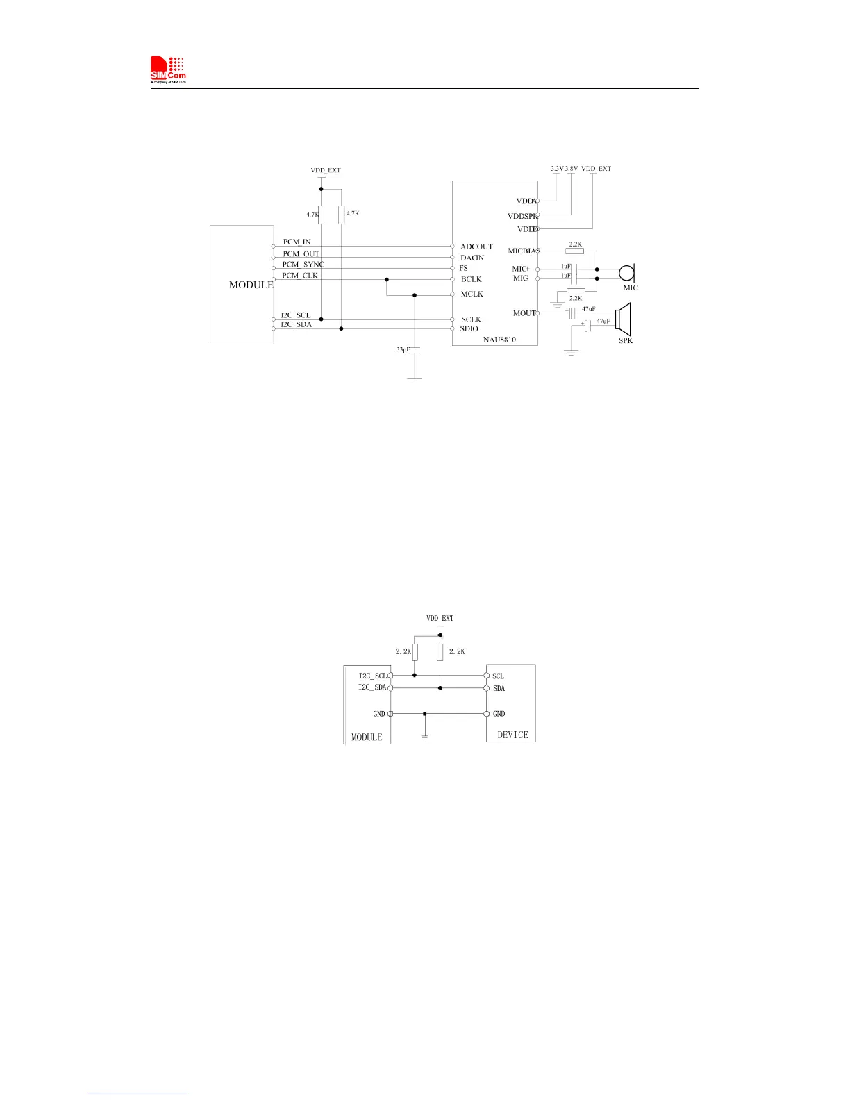
The following figure shows the external codec reference design.
Figure 24: Audio codec reference circuit
SIM7000 provides a I2C interface compatible with I2C specification, version 5.0, with clock rate
up to 400 kbps. Its operation voltage is 1.8V.
The following figure shows the I2C bus reference design.
Figure 25: I2C reference circuit
Note
:
I2C_SDA and I2C_SCL do not have pull-up resistors in module. So the two external
pulling up resistors are needed in application circuit.
“AT+CRIIC and AT+CWIIC” AT commands could be used to read/write register values of the
I2C peripheral devices. For more details about AT commands please refer to document [1].