Smart Machine Smart Decision
SIM7000 _Hardware Design _V1.00 2017-05-23
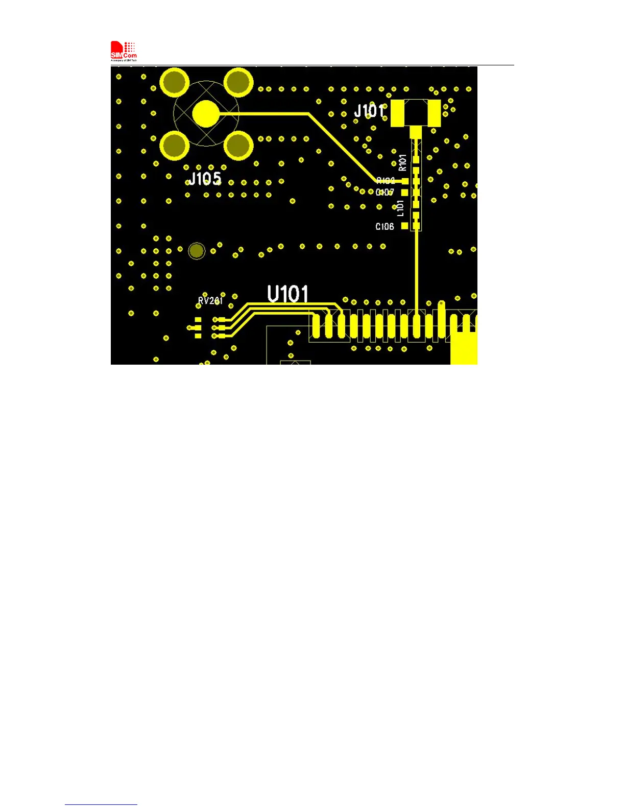
Figure 28: Antenna matching circuit (MAIN_ANT)
In figure 28, the components L101,C106,C107 and R101 or R102 are used for antenna matching,
the values of components can only be achieved after the antenna tuning and usually provided by
antenna vendor. By default, the L101,R101or R102 are 0Ω resistors, and the C106, C107 are
reserved for tuning. The RF test connector is used for the conducted RF performance test, and
should be placed as close as to the module’s MAIN_ANT pin. The traces impedance between
SIM7000 and antenna must be controlled in 50Ω.
SIM7000 merges GNSS (GPS/GLONASS/BD) satellite and network information to provide a
high-availability solution that offers industry-leading accuracy and performance. This solution
performs well, even in very challenging environmental conditions where conventional GNSS
receivers fail, and provides a platform to enable wireless operators to address both location-based
services and emergency mandates.