Make sure that the voltage on the VBAT pins will never drop below 3.0V, even during a transmit
burst, when current consumption may rise up to 2A. If the voltage drops below 3.0V, module will
be work abnormally.
Note: If the power supply for VBAT pins can support up to 2A, using a total of more than 300uF
capacitors is recommended, or else users must using a total of 1000uF capacitors typically, in
order to avoid the voltage drop is more than 300mV.
Some multi-layer ceramic chip (MLCC) capacitors (0.1uF, 1uF) with low ESR in high frequency
band can be used for EMC.
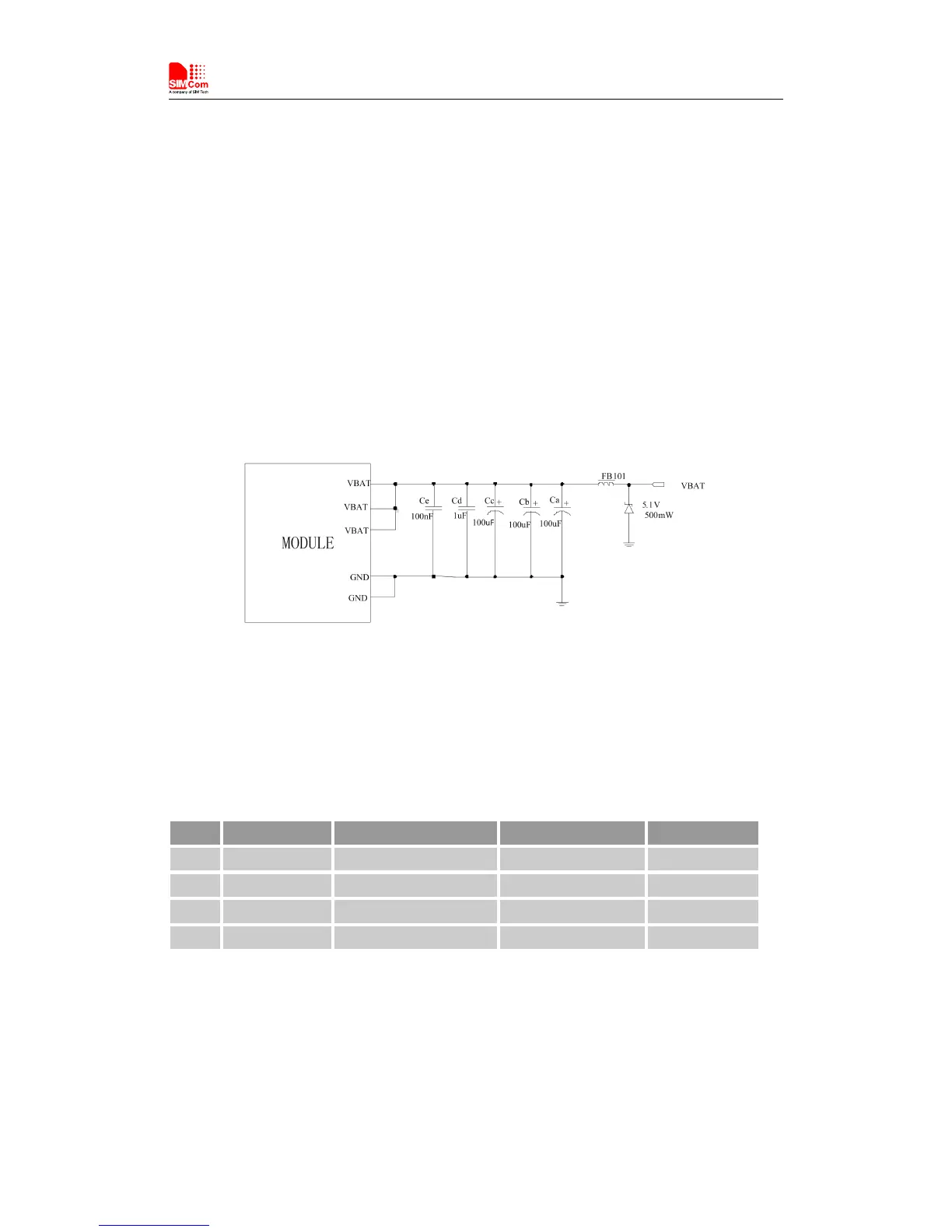
These capacitors should be put as close as possible to VBAT pads. Also, users should keep VBAT
trace on circuit board wider than 2 mm to minimize PCB trace impedance. The following figure
shows the recommended circuit.
Figure 6: Power supply application circuit
In addition, for over voltage protection, it is suggested to use a zener diode with 5.1V reverse
voltage and more than 500mW power dissipation.
Table 7: Recommended Zener diode list
It is recommended that a switching mode power supply or a linear regulator power supply is used.
It is important to make sure that all the components used in the power supply circuit can resist a
peak current up to 2A.