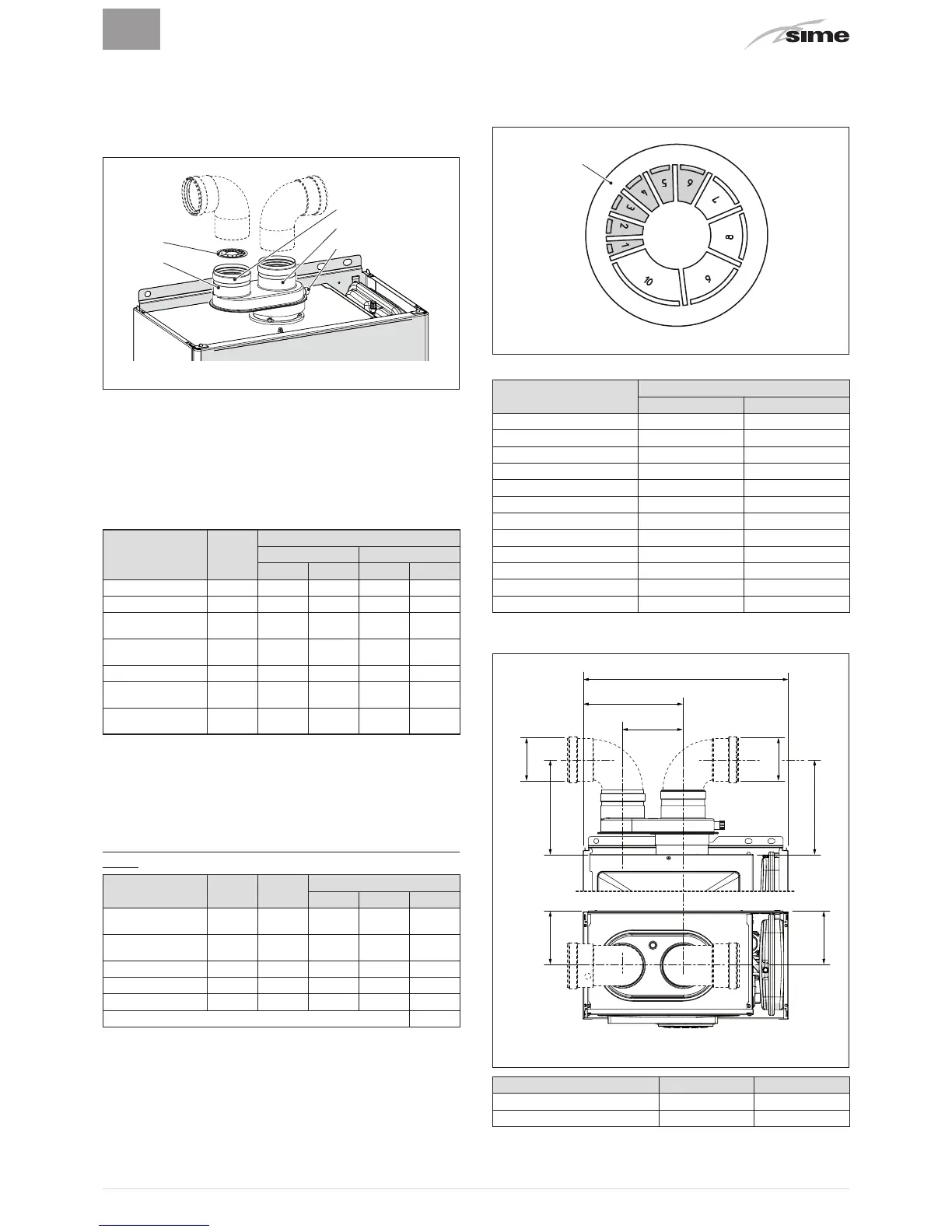
Split pipe system
The split pipe system is supplied with the combustion air inlet
diaphragm which is to be mounted, after the sections have
been eliminated according to the total load loss which is cal-
culated by summing the load losses of the inlet ducts to those
of the outlet ducts, as reported below.
1
2
4
5
3
Fig. 15
KEY:
1
Split pipe system with take-off point
2
Inlet diaphragm
3
Air inlet
4
Smoke outlet
5
Take-off point for smoke analysis
Load loss accessory Ø 80 mm
Description Code
Load loss (mm H2O)
Brava Slim 25 BF Brava Slim 30 BF
Inlet Outlet Inlet Outlet
90° curve MF
8077410
0,35 0,40 0,45 0,50
45° curve MF
8077411
0,30 0,35 0,40 0,45
Horizontal exten-
sion W. 1000 mm
8077309
0,20 0,30 0,25 0,35
Vertical extension
W. 1000 mm
8077309
0,20 0,10 0,25 0,15
Wall terminal
8089501
0,15 0,50 0,20 0,80
Condensate
recovery Tee
8093300
- 0,80 - 1,00
Roof outlet termi-
nal (*)
8091200
1,60 0,10 2,00 0,20
(*) The losses of the roof outlet terminal at inlet include the
manifold code 8091400.
NB:
for the boiler to operate correctly it is necessary that a
minimum distance of 0.50 m of the duct is respected with a
90° inlet curve.
Example: calculation of the load loss of a
Brava Slim 25 BF-
boiler.
Accessories Ø
80 mm
Code
Quan-
tity
Load loss (mm H2O)
Inlet Outlet Total
Extension W. 1000
mm (horizontal)
8077309
7 7 x 0,2 - 1,40
Extension W. 1000
mm (horizontal)
8077309
7 - 7 x 0,3 2,10
90° curve
8077410
2 2 x 0,35 - 0,70
90° curve
8077410
2 - 2 x 0,4 0,80
Wall terminal
8089501
2 0,15 0,5 0,65
TOTAL 5,65
(installation permitted since the total of the load loss of the
accessories used is less than 9.0 mm H2O).
With this total load loss, sections 1 to 6 (inclusive) must be
removed from the inlet diaphragm (2).
Fig. 16
No. of sections to be
removed
Total load loss (mm H2O)
Brava Slim 25 BF Brava Slim 30 BF
None 0 ÷ 2,0 0 ÷ 0,8
1 2,0 ÷ 3,0 0,8 ÷ 1,5
1 ÷ 2 3,0 ÷ 4,0 1,5 ÷ 2,4
1 ÷ 3 - 2,4 ÷ 3,2
1 ÷ 4 4,0 ÷ 5,0 3,2 ÷ 4,0
1 ÷ 5 - 4,0 ÷ 4,8
1 ÷ 6 5,0 ÷ 6,0 4,8 ÷ 5,6
1 ÷ 7 6,0 ÷ 7,0 5,6 ÷ 6,5
1 ÷ 8 - 6,5 ÷ 7,3
1 ÷ 9 7,0 ÷ 8,0 7,3 ÷ 7,8
1 ÷ 10 - 7,8 ÷ 8,4
Entire diaphragm 8.0 -
9.0
(*) 8.4 -
9.5
(*)
(*) Maximum load loss permitted.
120