m
CAUTION
It is compulsory:
– to use an omnipolar cut-off switch, disconnect
switch in compliance with EN Standards
– if the power cable is to be replaced, that ONLY a
special cable is used with a factory produced re-
wired connector, ordered as a spare part and con-
nected by a professionally qualified person
– to connect the earth wire to an effective earthing
system (*)
– that before any intervention on the boiler, the
mains power is disconnected by setting the main
system switch to "OFF".
(*) The manufacturer is not responsible for any damage
caused by failure to earth the appliance or failure to ob-
serve the information provided in the wiring diagrams.
d
IT IS FORBIDDEN
To use water pipes for earthing the appliance.
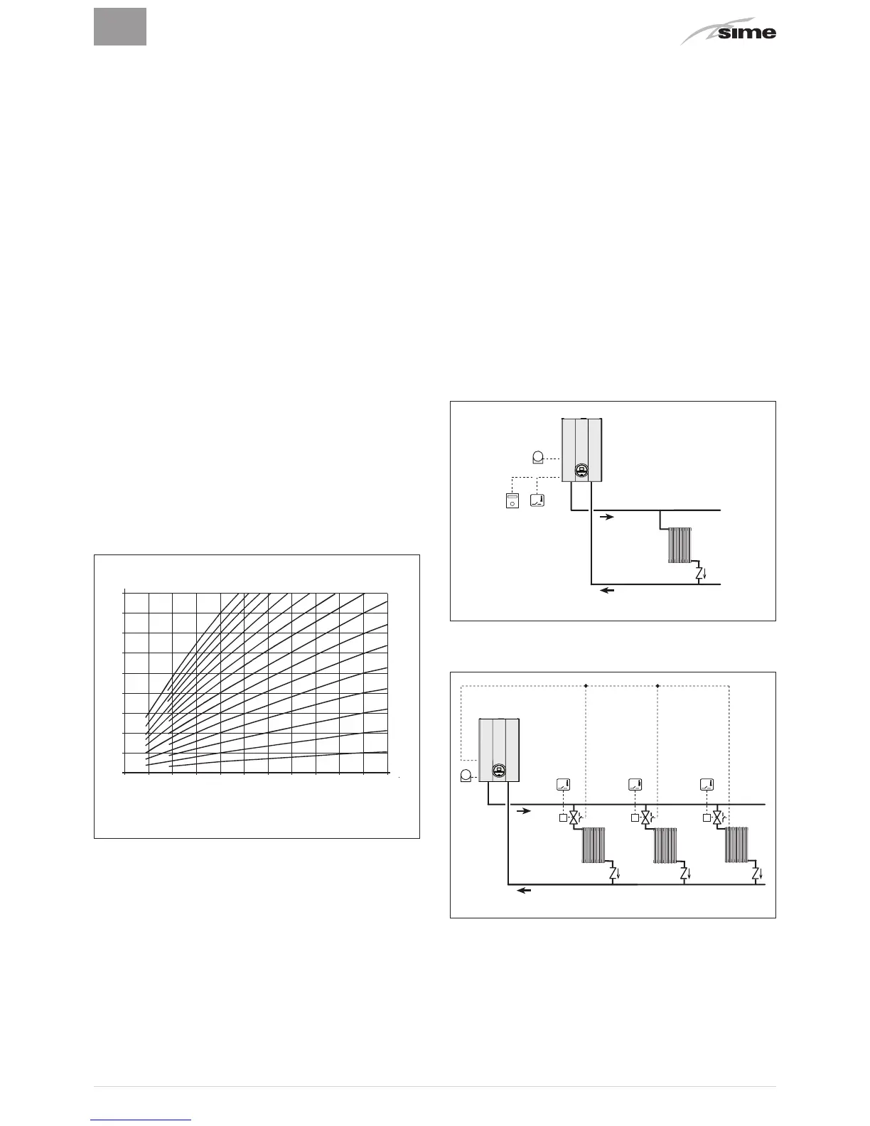
2.12.1 External sensor
The boiler is prearranged for connection to an external air
temperature sensor and can operate with a sliding temper-
ature.
This means that the delivery temperature sent to the boiler
can vary on the basis of the external temperature depending
on the climatic curve selected from those shown in the dia-
phragm (default curve no. 20).
When fitting the sensor on the outside of the building, follow
the instructions provided on the packaging of the product it-
self.
Climatic curve
Delivery temperature
20 10 0 -10 -20
External temperature
Fig. 23
m
CAUTION
The curves are calculated with a room temperature
of 20°C. To modify the curve, set "PAR. 12 = HEATING
CURVE INCLINE".
2.12.2 Chrono-thermostat or Air Thermostat
The electrical connection of the chrono-thermostat or air
thermostat has already been described. When fitting the com-
ponent in the room where the readings are to be taken, follow
the instructions provided on the packaging of the product it-
self.
2.12.3 EXAMPLE of use of the command/control
device on some types of heating systems
KEY
M System delivery
R System return
CR Remote control
SE External sensor
TA÷TA3 Air thermostat for the zone
VZ1-VZ3 Zone valves
RL1-RL3 Zone relays
P1-P3 Zone pump
SI Hydraulic separator
ONE DIRECT ZONE system , external sensor and air thermo-
stat or, alternatively, remote control.
R
M
SE
TA
 Loading...